


There are several parameters you can set in Rocky that will affect your overall simulation. These include various preferences and unit types, as well as variables and scripts. These items can be determined before you set up your simulation, or can be modified at any point during the setup process.
What would you like to learn about?
See Also:
Global preferences for Rocky include settings like memory usage, date and time format, video, plot and view options. What you choose to set in preferences will affect the rest of the Rocky user interface.
What would you like to do?
ABOUT SETTING GLOBAL PREFERENCES
When you set your global preferences, you determine what global (default) options you want to set for memory usage, date format, timestep format, drag and drop, Internet proxy, video encoding and quality, and display for Rocky windows, including 3D Views, plots, and histograms. You can also view (but not edit) what keyboard shortcuts perform which commands.
The settings that you choose in the Preferences dialog will persist throughout your entire Rocky experience. Some settings, like memory usage and Internet proxy settings, can only be changed from the Preferences dialog. Other settings, like window displays, affect only what default settings appear in the various panels within the Rocky UI but can be overridden from the panel whenever you want.
Important: Changes you make within the Preferences dialog may not immediately affect in-process features or functionality. To ensure that all changes you make within this dialog are applied immediately, click OK on the Preferences dialog, and then close and reopen any Rocky windows, panels, or projects affected by the Preferences changes you made.
PREFERENCES FOR NON-WINDOWS PROPERTIES
See the images and table below to help you understand what to set for your global preferences on properties not including those on the Windows panel.
PREFERENCES FOR WINDOWS PROPERTIES
The Properties settings listed under Windows on the Preferences dialog affect only the configuration used to create windows of the selected type. Any of these default settings can be overridden from the Window Editors panel whenever you want.
See the images and tables below to help you understand what global preferences to set for Windows panel-related items.
Also, see additional information on these settings in the following topics:
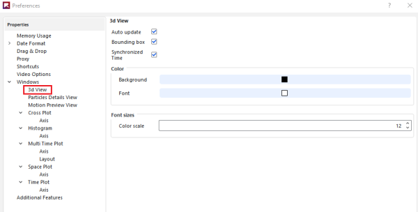
Table 2: Preferences options for 3d View Windows
|
Property |
Description |
Range |
|---|---|---|
|
Auto update |
When enabled, any change made to the display settings of the selected 3D View or to the items affecting the data or settings calculated and displayed within the 3D View, including the output time or Properties displayed, will be updated in the 3D View automatically. Because automatically updating the view with each separate change can be computationally intensive, you can clear this option to have all calculated items and more computationally intensive display options remain unchanged in the 3D View until you enable Auto update again. Tip: You will know when the calculations in a 3D View window are not being updated when you see a thick red border around the window. |
Turns on or off |
|
Bounding box |
When enabled, displays measurements illustrating the simulation entity in the selected 3D View. |
Turns on or off |
|
Synchronized Time |
When enabled and the window (or any other window with this checkbox enabled) is selected, the details shown in this (and any other Synchronized Time) window will be updated when the current output time is changed on the Time toolbar. (See also About the Time Toolbar.) When cleared and the window is selected, only this window will be updated when the current output time is changed on the Time toolbar. Tip: To keep the output time synchronized between multiple 3D View or other windows, ensure each window has this option enabled. |
Turns on or off |
|
Color Background |
Enables you to change the color that appears behind the geometries and particles in the 3D View. |
Options limited by the choices in the Select Color dialog |
|
Color Font |
Enables you to change the color of the labels, borders, and axes lines displayed in the 3D View. Note: These color options can be overridden for text overlays by using the Color option on the Overlays tab. (See Table 3 below.) |
Options limited by the choices in the Select Color dialog |
|
Font sizes Color scale |
Enables you to change the size of the text used on color scales for Properties, which, unlike the other lines or labels displayed on the 3D View, is not affected by the window size or the level of zoom you have applied. |
Whole values from 1 to 100 |
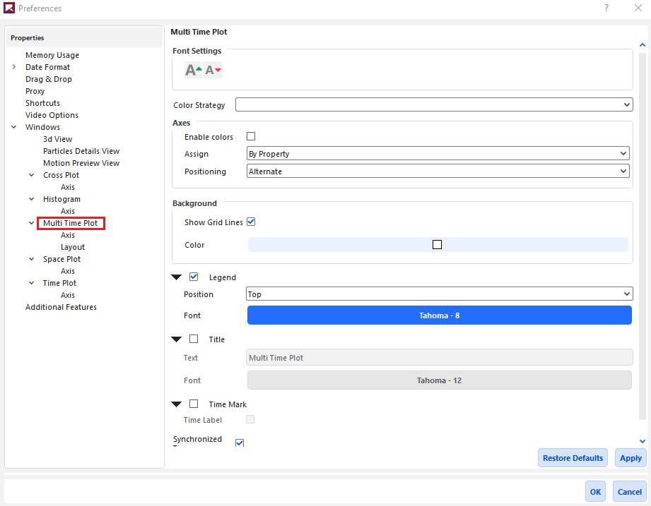
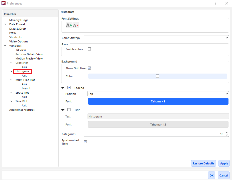
Table 3: Preferences options for Graph (Plot and Histogram) Windows
|
Setting |
Description |
Range |
|---|---|---|
|
Font Settings |
The following two buttons in this section apply to all axes, legend, and title text shown in the graph:
Notes:
|
Increase font size; Reduce font size |
|
Color Strategy |
Changes the coloring criteria of the curves, which affects the legend text and plot line of the properties (Property or Curves) being graphed. This option can be used to group curves with a similar representation by color based upon the following options:
|
Entity Based; Property Based; Unique |
|
Axes Enable colors |
Enabling this checkbox colors the Y axes according to the Color Strategy selected. Clearing this checkbox keeps all axes colored black. |
Turns on or off |
|
Axes Assign |
For plots with multiple Properties or Curves, this enables the Y axes to be shared according to the following options:
|
By Quantity; By Property |
|
Axes Positioning |
For plots only, this sets on which side of the graph the axes will be displayed. Specifically:
|
Alternate; Left Axes First; Right Axes First |
|
Background Show Grid Lines |
Selecting this checkbox enables black grid lines to appear behind your graph. |
Turns on or off |
|
Background Color |
Enables you to choose the color that appears behind your graph. |
Options limited by the Select Color dialog |
|
Legend |
Enables the legend information, the content and color of which are determined by the Color Strategy setting, to be displayed on the graph window. |
Turns on or off |
|
Legend Position |
When Legend is enabled, determines where the Legend information appears on your graph. |
Bottom; Left; Right; Top |
|
Legend Font |
Enables you to change the type, style, size, and effects of the font used for displaying the Legend text. Note: The size you choose will still be affected by the Font Settings buttons. |
Options limited by the Select Font dialog |
|
Time Mark |
For Time and Multi Time Plots only, enables a dotted, vertical line to be displayed at the location of the current output time. |
Turns on or off |
|
Time Label |
When Time Mark is selected, enables you to add a label to the mark displaying the current output time value. Note: The value displayed reflects the units used for the Time (X) axis. |
Turns on or off |
|
Title |
Enables you to add a separate title to the top of the graph. |
Turns on or off |
|
Title Text |
When Title is selected, determines what text will be displayed in the title. |
No limit |
|
Title Font |
Enables you to change the type, style, size, and effects of the font used for displaying the Title text. Note: The size you choose will still be affected by the Font Settings buttons. |
Options limited by the Select Font dialog |
|
Categories (same as Number of Bins elsewhere) |
For histograms only, enables you to choose the number of bins or bars the data is aggregated into. |
Whole numbers greater than 1 |
|
Synchronized Time |
When enabled and the plot window (or any other window with this checkbox enabled) is selected, the details shown in this (and any other Synchronized Time) window will be updated when the current output time is changed on the Time toolbar. (See also About the Time Toolbar.) When cleared and the window is selected, only this window will be updated when the current output time is changed on the Time toolbar. Tip: To keep the output time synchronized between multiple plot or other display windows, ensure each window has this option enabled. |
Turns on or off |
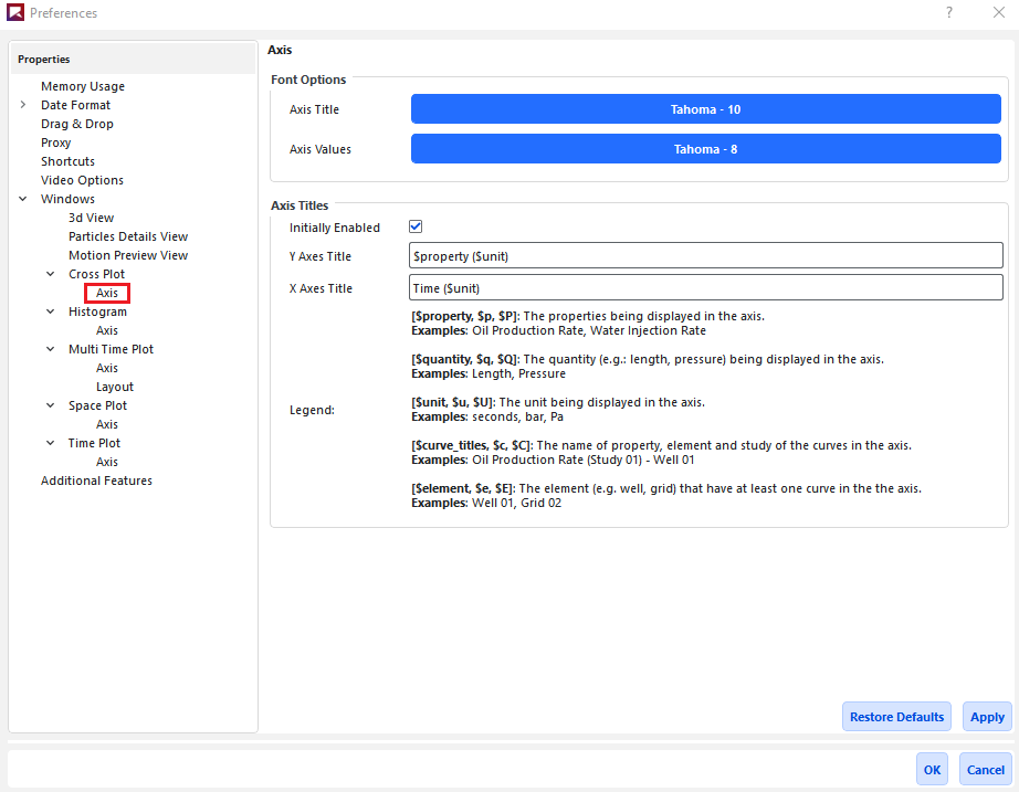
Table 4: Preferences options for Axes on Graph (Plot and Histogram) Windows
|
Setting |
Description |
Range |
|---|---|---|
|
Font Options | ||
|
Axis Title |
Enables you to change the type, style, size, and effects of the font used for displaying the title Text for the selected axis. Note: The size you choose will still be affected by the Font Settings buttons located on the first tab of the Window Editors panel. |
Options limited by the Select Font dialog |
|
Axis Values |
Enables you to change the type, style, size, and effects of the font used for displaying the value marks for the selected axis. Note: The size you choose will still be affected by the Font Settings buttons located on the first tab of the Window Editors panel. |
Options limited by the Select Font dialog |
|
Axis Titles | ||
|
Initially Enabled |
When selected, default axis titles will be added to the plot. When cleared, no axis titles will appear by default; you must manually turn on Axis Title from the Window Editors panel when you want an axis title to show. |
Turns on or off |
|
Y Axes Title |
Enables you to specify the default format for titles appearing on the Y axis. Any Keywords you specify will be replaced with the corresponding data in the Axes Title field, and will be updated when the data supporting the Keyword changes. Tip: Sample Keywords are provided in the Legend section. |
No limit |
|
X Axes Title |
Enables you to specify the default format for titles appearing on the X axis. Any Keywords you specify will be replaced with the corresponding data in the Axes Title field, and will be updated when the data supporting the Keyword changes. Tip: Sample Keywords are provided in the Legend section. |
No limit |
|
Legend |
Displays sample Keywords you can use when defining Axes Title information. |
Display only |
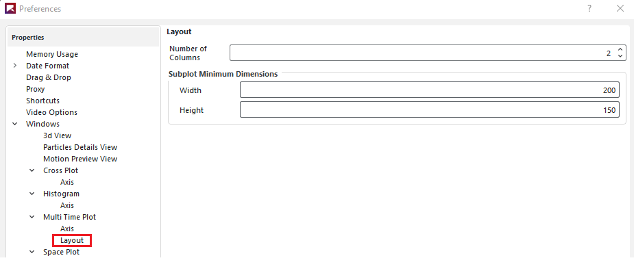
Table 5: Preferences options for Layout on Multi Time Plot Windows
|
Setting |
Description |
Range |
|---|---|---|
|
Number of Columns |
Enables you to set how many columns into which you want the sub-plots of your selected Multi Time Plot arranged. |
Whole numbers greater than or equal to one |
|
Subplot Minimum Dimensions Width |
Enables you to define the minimum pixel width you want Rocky to maintain for each individual sub-plot in the selected Multi Time Plot. When making the window size smaller, the sub-plots will continue to be displayed in full until this setting is reached, at which point scroll bars will be added. |
Whole values greater than or equal to 300 |
|
Subplot Minimum Dimensions Height |
Enables you to define the minimum pixel height you want Rocky to maintain for each individual sub-plot in the selected Multi Time Plot. When making the window size smaller, the sub-plots will continue to be displayed in full until this setting is reached, at which point scroll bars will be added. |
Whole values greater than or equal to 150 |
What do you want to do?
See Also:
From the Options menu, click Preferences.
From the Preferences dialog, choose the category you want under Properties, and then make the choices you want on the right. Note: Shortcuts are not currently editable.
Click Apply to save your changes.
Repeat steps 2-3 until you have set all the options you want, and then click OK to close the dialog. Tip: To ensure that all changes you made within this dialog are applied immediately, close and reopen any Rocky windows, panels, or projects affected by the Preferences changes you made.
See Also:
Before you begin using Rocky, it is important that you understand the units used in the user interface and set them the way you want.
What would you like to do?
See Also:
ABOUT SETTING YOUR UNIT SYSTEM
Currently, there are two unit systems included in Rocky: the International System and the English. You can choose to use one of these two included systems, or you can create your own custom unit system.
Whatever system you choose will provide the default unit settings for all parameters used within Rocky. However, each individual parameter unit can still be changed manually to another unit type at any time.
Use the images and tables below to help you understand your unit system options.
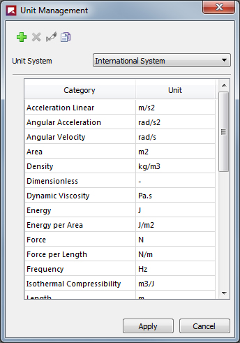 Figure 1 : Unit Management
dialog
Figure 1 : Unit Management
dialog
Table 1: Unit Management dialog options
|
Setting |
Description |
Range |
|---|---|---|
|
Unit System |
Sets the unit system used by default throughout Rocky. Choices include:
If you have created custom unit systems, those will display in this list also. |
Lists all default and custom unit systems for Rocky. |
|
Category |
Lists the descriptive name of the item being measured. |
Automatic |
|
Unit |
Provides the unit symbol that will be used by default for the parameters in Rocky. These are editable when you choose to create a custom system. |
Automatic |
Table 2: Default Units Used in Rocky
|
Item |
International Unit |
International Unit Symbol |
English Unit |
English Unit Symbol |
|---|---|---|---|---|
|
Acceleration Linear |
meter per second squared |
m/s2 |
foot per second squared |
ft/s2 |
|
Angular Acceleration |
radian per second squared |
rad/s2 |
radian per second squared |
rad/s2 |
|
Angular Velocity |
radian per second |
rad/s |
radian per second |
rad/s |
|
Area |
square meter |
m2 |
square foot |
ft2 |
|
Density |
kilogram per cubic meter |
kg/m3 |
pound mass per cubic foot |
lbm /ft3 |
|
Dimensionless |
- |
- |
- |
- |
|
Dynamic Viscosity |
Pascal second |
Pa⋅s |
centipoise |
cP |
|
Energy |
joule |
J |
foot pound force |
ft⋅ lbf |
|
Energy per Area |
joule per meter squared |
J/m 2 |
pound force per foot |
lbf /ft |
|
Force |
Newton |
N |
pound force |
lbf |
|
Force per Length |
Newton per meter |
N/m |
pound force per foot |
lbf /ft |
|
Frequency |
hertz |
Hz |
hertz |
Hz |
|
Isothermal Compressibility |
cubic meter per joule |
m3/J |
cubic meter per joule |
m3/J |
|
Kinematic Viscosity |
square meter per second |
m2/s |
centistoke |
cSt |
|
Length |
meter |
m |
foot |
ft |
|
Mass |
kilogram |
kg |
pound mass |
lbm |
|
Mass Flow Rate (formerly "Tonnage") |
metric tons per hour |
t/h |
pound mass per hour |
lbm /h |
|
Mass per Energy |
kilogram per joule |
kg/J |
pound mass per foot pound force |
lbm / ft⋅lbf |
|
Moment of Force (formerly "Torque") |
Newton meter |
N⋅m |
foot pound force |
ft⋅lbf |
|
Moment of Inertia |
kilogram meter squared |
kg⋅m2 |
square foot pound mass |
lbm⋅ ft2 |
|
Percentage |
Percentage |
% |
Percentage |
% |
|
Plane Angle |
angular degree |
dega |
angular degree |
dega |
|
Poisson Ratio |
- |
- |
- |
- |
|
Power |
watts |
W |
horsepower |
hp |
|
Power per Mass |
watts per kilogram |
W/kg |
watts per kilogram |
W/kg |
|
Pressure |
Pascal |
Pa |
pound-force per square inch |
psi |
|
Specific Energy |
joules per kilogram |
J/kg |
foot pound force per pound mass |
ft⋅ lbf /lbm |
|
Thermodynamic Temperature |
Kelvin |
K |
degrees Fahrenheit |
degF |
|
Time |
second |
s |
second |
s |
|
Velocity |
meter per second |
m/s |
feet per second |
ft/s |
|
Volume |
cubic meter |
m3 |
cubic feet |
ft3 |
|
Yield Stress |
force per unit area |
N/m2 |
pound force per square foot |
lbf /ft2 |
What would you like to do?
See Also:
SELECT A UNIT SYSTEM TO USE THROUGHOUT ROCKY
From the Options menu, click Unit System Manager.
From the Unit Management dialog, choose the option you want from the Unit System list.
Click Apply to save your changes and close the dialog.
See Also:
From the Options menu, click Unit System Manager.
From the Unit Management dialog, do one of the following:
To create a new unit system based upon an existing one, choose the option you want to copy from the Unit Systems list, and then click the Copy the current Unit System button. A copy of the existing system is created.
To create a new blank system, press the Create a new Unit System button. A blank system is created.
Click the Rename the current Unit System button and then in the Enter the new name box, type the name you want and then click OK.
Edit the system list as you want.
Click Apply to save your changes and close the dialog.
See Also:
From the Options menu, click Unit System Manager.
From the Unit Management dialog, choose the custom unit system you want to edit from the Unit System list. Note: You can edit only the custom unit systems that you have added. If you want to edit the International or English system units included in Rocky, you must first make a copy of those systems and then edit the copy.
Do one or more of the following:
To change the units used, choose the option you want from the Unit list.
To add a new category, click the Add button, and then from the Add Category dialog, choose the options you want in the Category and Unit lists, and then click OK.
To remove a category, select the category you want to remove and click the Remove button.
Click Apply to save your changes and close the dialog.
See Also:
From the Options menu, click Unit System Manager.
From the Unit Management dialog, choose the custom unit system you want to remove from the Unit System list, and then click the Remove the Current Unit System button. Note: You can only remove custom unit systems that you have created. The International and English system units included in Rocky are not removable.
Click Apply to save your changes and close the dialog.
See Also:
The Expressions/Variables tool in Rocky enables you to define unique placeholders for both Input variables (values used within the Rocky set up parameters) and Output variables (values that are exported out of Rocky into programs like Ansys Workbench for tasks like structural analysis). The variables you define can then be used in place of actual numerical values within the parameter text fields. This is useful in cases where you have common values that are linked (all belts are to be the same width, for example), and/or the values you enter might be changing later in the setup (you want to experiment with three different belt speeds, for example).
What would you like to learn more about?
See Also:
DEFINING AND USING INPUT VARIABLES
Using Input variables is also a good way to make complicated project setups simpler and easier to verify then by manually entering the same information into many different parameter field locations.
What would you like to do?
See Also:
ABOUT DEFINING AND USING INPUT VARIABLES
For Input variables, you can enter into the parameter text fields a variable name on its own, or you can use a variable within a mathematical function that you enter into the parameter text field instead. In this way, Rocky enables you to create dynamic relationships between parameters, and enables you to change and update placeholder values quickly. Using Input variables is also a good way to make complicated project setups simpler and easier to verify then by manually entering the same information into many different parameter field locations.
But because it can be hard to remember what parameters use what variables, Rocky uses the Expressions list to help you keep track of where the Input variables are being referenced-even if it is being used within a function or other variable definition. The Expressions list is also useful for verifying what units the variable or function is using for the particular location specified, and for changing the value or units of the variable later without having to locate it again in the Data Editors panel.
Setting Input Variables
Important:Verify that your field units are set the way you want before using or creating a variable-or function including a variable-within a field. Even though variables are saved in the Variables list without units, as soon as a variable-or function including a variable-is used within a parameter field, it takes on whatever units are currently set for that field and those units are then recorded for that specific usage in the Expressions list. Changing the units for the field after the variable or function have already been entered only converts the numerical display to reflect the new units; the original variable or function amount and units are still retained. However, you can change the units and value later by editing it in the Expressions list.
Input variables can be defined and used at any point during the setup portion of your simulation. (See also Enter Input Variables or Mathematical Functions as Parameter Values.) Most text fields in Rocky support entering variables or mathematical functions as parameter variables, including three-part text fields.
Most text fields will also support the entering of pre-defined mathematical functions (e.g., floor and pow) and constants (e.g., pi and e) that come standard with Python-based programs, including Rocky. And as such, these particular functions and constants cannot be used when defining Input variables.
Using Input Variables with Ansys Workbench
Input variables are also useful when setting up Ansys Workbench-connected projects as you can use Workbench's Design Points functionality to replace Input Variables from Rocky with new values. When used together with Rocky's Output Variables, this functionality helps you more easily iterate upon simulation and setup components.
Note: To see walk-through examples of using Input Variables within Workbench-connected projects, refer to the following:
Input Variables Parameter Definitions
Use the images and tables below to help you understand how to set your Input variables.

Figure 2.149: The variable name and units used for the field appears after double-clicking the field
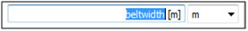
Figure 2.150: The current value for the variable entered appears in the field after clicking away from the field
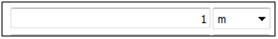
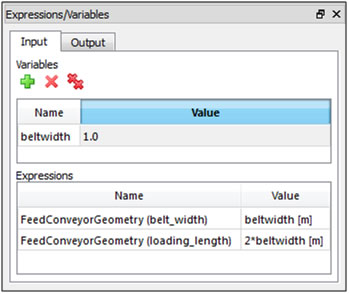 Figure 4: Expressions/Variables panel, Input tab
showing one defined variable being used in two separate locations
Figure 4: Expressions/Variables panel, Input tab
showing one defined variable being used in two separate locations
Table 1: Expressions/Variables panel, Input tab options
|
Setting |
Description |
Range |
|---|---|---|
|
Variables | ||
|
Name |
Enables you to specify a unique identifier for the variable. |
The name must begin with a letter or underscore and can be followed by as many letters, underscores, or numbers as desired. Spaces and other symbols are not allowed. Letters are case sensitive. |
|
Value |
The numeric value-or a function including other existing variable(s)-assigned to the variable name. |
Any value; or any valid mathematical function including other existing variable(s), as long as the function does not create an infinite loop. (For more information about using functions, see Enter Input Variables or Mathematical Functions as Parameter Values.) |
|
Expressions | ||
|
Name |
Lists the parameter field and location being used by the variable listed in the Value column. |
Automatically provided. Cannot be edited. |
|
Value |
Lists the variable Name and the units it is currently using within the field specified by the Expression Value column. |
Automatically provided. Tip: Double-click the value to edit the units. (See also Change the Units for an Input Variable-or Functions Using Input Variables-in Use by a Field.) |
What would you like to do?
See Also:
CREATE A NEW INPUT VARIABLE FROM WITHIN A PARAMETER FIELD
Note: This method works only when using numerical values to define the variable. If for the variable definition, you want to reference other existing variable(s) within a function, you must define the new variable using the Expressions/Variables panel.
Ensure the units for the field are set the way you want. Important:Though the variable itself will be saved without units, its use in this particular field will be affected by the units that are displayed during the next step.
Directly into the field in which you want to use the variable, enter a name for the new variable, and then press Enter. Tips: The name must begin with a letter and must have no spaces. Only letters, numbers, and underscores are recognized (no symbols). Letters are case sensitive. The nme must not include pre-defined mathematical functions nor constants.
In the Variable Creation dialog, enter a numerical value for the variable, and then click Create variable. You will notice all of the following events:
The variable name is replaced by the numerical value in the parameter field. The variable is also using the units that were set for that field when the variable was entered. Tip: Double-click the field to see the full variable name and the units that it is using.
The new variable is displayed in the following two places on the Input tab of the Expressions/Variables panel (from the Tools menu, click Expressions/Variables):
Under Variables, where it is saved without units for use in other parameter fields. Tip: You can edit both the name and the value by double-clicking the information you want to change. (See also Edit the Name of an Existing Input Variable or Edit the Value of an Existing Input Variable.)
Under Expressions, where the variable name and units applied in that particular usage are saved along with the location of its use. Tip: You can edit the value and units recorded here by double-clicking the information in the Value column, and then modifying anything before the closing bracket.
See Also:
EDIT THE VALUE OF AN EXISTING INPUT VARIABLE
From the Input tab on the Expressions/Variables panel (from the Tools menu, click Expressions/Variables), double-click the Value for the variable Name you want to change. The Value field for that variable becomes active.
Enter the new value you want and then press Enter. The new value is saved. Notes:
The variable value is always saved without units. When used in a field, this variable will use in that instance whatever units are currently being displayed for that field.
Once used in a field, you cannot change from the field the units being used by the variable in that particular field. (See also Change the Units for an Input Variable—or Functions Using Input Variables-in Use by a Field.) You can, however, change the units by modifying the Value information in the Expressions/Variables panel under Expressions. Just double-click the Value you want to change, and then modify anything you want before the closing bracket.
See Also:
EDIT THE NAME OF AN EXISTING INPUT VARIABLE
From the Input tab on the Expressions/Variables panel (from the Tools menu, click Expressions/Variables), double-click the Name for the variable you want to change. The Name field for that variable becomes active.
Enter the new name you want and then press Enter. The new name is saved in the panel and is also replaced in any field making use of the variable.
See Also:
CHANGE THE UNITS FOR AN INPUT VARIABLE-OR FUNCTIONS USING INPUT VARIABLES-IN USE BY A FIELD
Do one of the following:
In the Expressions/Variables panel under Expressions, find the instance of the variable whose units you want to change, double-click the Value for that usage, and then modify the units displayed in the brackets.
Remove the variable name-or function using the variable name-from the field, set the units for the field to the ones you want adopted by the variable or function, and then re-enter the variable name-or function using the variable name-again. Tip: Double-click the field to see the full variable name-or function using the variable name-and the units that it using in that instance.
See Also:
REMOVE A SINGLE INPUT VARIABLE
From the Input tab of the Expressions/Variables panel, select the Name of the variable you want to remove, and then click the Remove button. Just that variable is removed from the list.
Note: The last value replaces the variable name in any parameter field the removed variable was being used, and the Expressions list recording for that variable is cleared.
See Also:
From the Input tab of the Expressions/Variables panel, select a variable to enable the buttons, and then click the Remove All button. All the variables in the list on that tab are removed from the list.
Note: The last values replace all the respective variable names in any parameter field the removed variables were being used, and the Expressions list recordings for the all the variables are cleared.
See Also:
Defining output variables enable you to distill a set of data points from a Property or Curve into a single final value.
What would you like to do?
See Also:
ABOUT DEFINING OUTPUT VARIABLES
Output variables enable you to distill a set of data points from a Property or Curve into a single final value. (See also Use Properties and Curves.) This process is illustrated in the example provided in Figure 1 below.
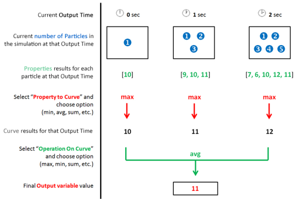 Figure 1 : Example of how Output variables are
distilled into one value from a data set you define
Figure 1 : Example of how Output variables are
distilled into one value from a data set you define
In this example, the output time for the data set is limited to the first three seconds of the simulation, which then gives us the number of particles available at each of those three outputs. Then, the Property value for each particle at each of the three outputs is provided. Those Property values are then distilled into a single-value Curve for each output time, in this case the maximum value out of each of the three Property data sets is selected. Out of the three resulting Curve values, one last distillation, in this case by average value, gives us the final value that will be saved to the Output variable, in this case, 11.
USING OUTPUT VARIABLES INSTEAD OF PLOTS
You can use Output variables as an alternative to generating and measuring data in Time plots. (See also About Graphing (Plot or Histogram) a Data Set Within Rocky). Unlike a Time plot, an Output variable allows you to distill a set of Property or Curve values into a single value in one, easy-to-find location. For example, this method would be a benefit when needing to calculate the average mass of particles in a particular cube-shaped portion of the simulation between 3 and 10 seconds simulation time. (See also Filter Views and Data with User Processes.)
USING OUTPUT VARIABLES WITH ANSYS WORKBENCH
You can also use Output variables to distill data into a single value for exporting out of Rocky and into an Ansys Workbench project. When used together with Rocky's Input Variables, Workbench's Design Points functionality enables you to replace Input Variables from Rocky with new values, and then have Rocky provide the resulting Output value, all of which helps you more easily iterate upon simulation and setup components.
Tip: To see walk-through examples of using Output Variables within Workbench-connected projects, refer to the following Tutorials:
OUTPUT VARIABLES PARAMETER DEFINITIONS
Use the images and table below to help you understand how to define Output variables.
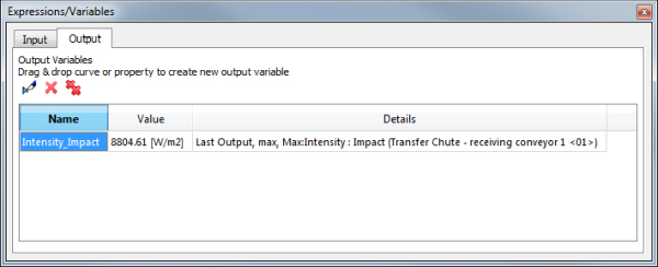 Figure 2: Expressions/Variables panel, Output tab
showing one defined Property variable
Figure 2: Expressions/Variables panel, Output tab
showing one defined Property variable
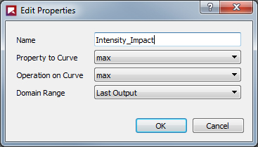
Table 1 : Expressions/Variables panel, Output tab and Edit Properties dialog options
|
Setting |
Description |
Range |
|---|---|---|
|
Name |
Enables you to specify a unique identifier for the variable. By default, it is the name of the Curve or Property that you have chosen but can be edited as desired. |
The name must begin with a letter or underscore and can be followed by as many letters, underscores, or numbers as desired. Spaces and other symbols are not allowed. Letters are case sensitive. |
|
Value |
The numerical value assigned to the variable as determined by the Curve or Property that you have chosen and the constraints you have assigned. |
Automatically calculated based upon the settings you have chosen. |
|
Details |
A summary of the constraints imposed upon the Curve or Property that results in the Value displayed. |
Automatically listed based upon the settings you have chosen. |
|
Property to Curve |
When the variable is based upon a Property, this is the function that will convert the Property values at each output time in the Domain Range to a single value. This single value will then be acted upon by the Operation on Curve function to get the final Value. |
Min; Max; Average; Sum; Sum Squared; Variance; Standard Deviation For more information, see Use Properties and Curves. |
|
Operation on Curve |
If the variable is based upon a Curve, this is the operation that will be applied to it to generate the final Value for the variable. If the variable is based upon a Property, this is the operation that will be applied to the single value generated from the Property to Curve value to achieve a final Value for the variable. |
Min; Max; Average; Sum; Sum Squared; Variance; Standard Deviation For more information, see Use Properties and Curves. |
|
Domain Range |
Defines what Output Times of the simulation are included in the final Value calculation. The options are as follows:
|
Application Time Filter; All; Last Output; Time Range; Specify Time; After Time; Time Range Relative to Simulation End |
|
Initial |
When Time Range or After Time is chosen for Domain Range, this is the starting time to begin calculations. |
Any value between 0 and the final simulation time. |
|
Final |
When Time Range is chosen for Domain Range, this is the ending time when calculations are stopped. |
Any value between the Initial time and the final simulation time. |
|
At Time |
When Specific Time is chosen for Domain Range, this is the exact moment in which the calculation will be performed. |
Any value between 0 and the final simulation time. |
|
Range from end |
When Time Range Relative to Simulation End is chosen for Domain Range, this is the period of time before the final simulation time in which output times will be included in the calculation. For example, when you want to include only the last X seconds of the simulation. |
Any value between 0 and the final simulation time. |
What would you like to do?
See Also:
Set up and process the simulation as you normally would.
Do all of the following: - Select the Curve or Property tab that contains the information you are interested in. (From the Data panel, select Particles, the geometry, or user process for which you want data and then in the Data Editors panel, select the tab for which you are interested.) - Click and drag the Name of the data you want to the Output tab of the Expressions/Variables panel. (From the Tools menu, click Expressions/Variables.) - Release the mouse. The data appears as a new variable in the Output list.
See Also:
EDIT THE DETAILS OF AN OUTPUT VARIABLE
From the Output tab of the Expressions/Variables panel, select the Name of the variable you want to edit, and then click the Edit button.
From the Edit Properties dialog, enter the information you want as explained in Table 1, and then click OK.
See Also:
REMOVE A SINGLE OUTPUT VARIABLE
From the Output tab of the Expressions/Variables panel, select the Name of the variable you want to remove, and then click the Remove button. Just that variable is removed from the list.
See Also:
From the Output tab of the Expressions/Variables panel, select a variable to enable the buttons, and then click the Remove All button. All the variables in the list on that tab are removed from the list.
See Also: