


Modeling is a two-part task, as described in the following sections:
Two rectangular shaped plates (similar to those used in the reference model) are used as the workpiece. Dimensions have been reduced to decrease the simulation time.
The plate size is 3 x 1.25 x 0.125 in (76.2 x 31.75 x 3.18 mm). The tool shoulder diameter is 0.6 in (15.24 mm).
The plate thickness remains the same as that of the reference model, but the plate length and width are reduced. The plate width is reduced because the regions far from the weld line are not significantly affected by the welding process, and this example focuses primarily on the heat generation and temperature rise in the region nearest the weld line.
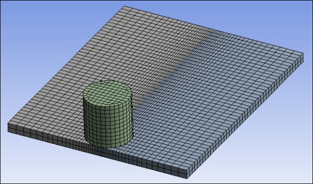
The height of the tool is equal to the shoulder diameter. Both the workpiece (steel plates) and the tool are modeled using coupled-field element SOLID225 with the structural-thermal physics definition activated in the Physics Region object details (see Analysis and Solution Controls). The Brick Integration Scheme property is set to in geometry details.
A hexahedral mesh with lower order elements is used because the presence of midside nodes (or quadratic interpolation functions) can lead to oscillations in the thermal solution and a nonphysical temperature distribution. A hexahedral mesh is used instead of a tetrahedral mesh to avoid mesh-orientation dependency. For more accurate results, a finer mesh is used in the weld-line region. The following figure shows the 3-D meshed model.
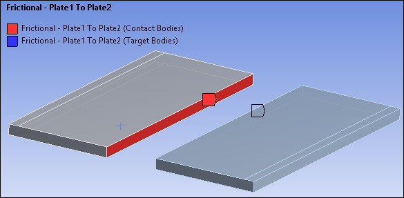
Contact is modeled as follows for the FSW simulation:
During the simulation, the surfaces to be joined come into contact, modeled as a standard surface-to-surface contact pair using TARGE170 and CONTA174, as shown below.
The surface-projection-based contact method (KEYOPT(4) = 3 for contact elements) is defined at the contact interface. The surface-projection-based contact method is well suited to highly nonlinear problems that include geometrical, material, and contact nonlinearities.
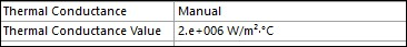
The problem simulates welding using the bonding capability of contact elements. To achieve continuous bonding and simulate a perfect thermal contact between the plates, a high thermal contact conductance (TCC) of 2E06 W/m2 °C is specified. (A small TCC value yields an imperfect contact and a temperature discontinuity across the interface.) The thermal conductance is specified as a Real Constant for CONTA174 elements in the details of the contact region object as shown in the following screenshot.
The maximum temperature ranges from 70 to 90 percent of the melting temperature of the workpiece material. Welding occurs after the temperature of the material around the contacting surfaces exceeds the bonding temperature (approximately 70 percent of the workpiece melting temperature). In this case, 900 °C is taken as the bonding temperature based on the reference results. The bonding temperature is specified using the real constant TBND for CONTA174. When the temperature at the contact surface for closed contact exceeds the bonding temperature, the contact type changes to bonded, and it remains bonded for the remainder of the simulation, even though the temperature subsequently decreases below the bonding value.
Note: Use the command snippet below to set the bonding temperature since there is no option for setting this in the Mechanical Application. For information on adding command snippets in Mechanical, see Commands (APDL).

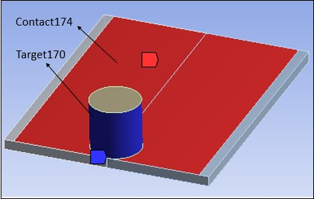
The tool plunges into the work piece, rotates, and moves along the weld line. Because the frictional contact between the tool and workpiece is primarily responsible for heat generation, a standard surface-to-surface contact pair is defined between the tool and workpiece. The CONTA174 element is used to model the contact surface on the top surface of the workpiece, and the TARGE170 element is used for the tool, as shown in the following figure.
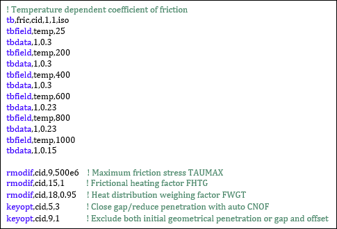
You must specify two real constants to model friction-induced heat generation: the friction heat factor (FHTG) and the dissipation weight factor (FWGT). The friction heat factor (FHTG) is the fraction of frictional dissipated energy converted into heat. FHTG is set to 1 to convert all frictional dissipated energy into heat. The weight factor for the distribution of heat between the contact and target surfaces (FWGT) is set to 0.95 so that 95 percent of the heat generated from the friction flows into the workpiece and only five percent flows into the tool [2].
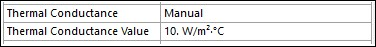
A low TCC value (10 W/m2 °C) is specified for this contact pair because most of the heat generated transfers to the workpiece.
Some additional heat is also generated by plastic deformation of the workpiece material. Because the workpiece material softens and the value of friction coefficient drops as the temperature increases [3], a variable coefficient of friction (0.3 to 0.15) is defined using a command snippet issuing TB,FRIC with TBTEMP and TBDATA, (see note below).
Note: Although there is no option to set a variable coefficient of friction in the Mechanical Application, it can be done with a command snippet, as shown below. For information on using command snippets in Mechanical, see Snippets and Scripting in Mechanical.
Finally, set Contact Type to Frictional and Coefficient of Friction to 0 in the Details view of Contact.