


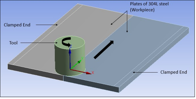
A direct coupled-field analysis is performed on a reduced-scale version of the Zhu and Chao model [1]. Also, rather than using a moving heat source as in the reference model, a rotating and moving tool is used for a more realistic simulation. The tool pin is ignored. The heat generated at the pin represents approximately two percent of the total heat and is therefore negligible. The simulation welds two 304L stainless steel plates (workpiece) with a cylindrical shape tool, as shown in the following figure.
The FSW process generally requires a tool made of a harder material than the workpiece material being welded. In the past, FSW was used for soft workpiece materials such as aluminium. With the development of tools made from super-abrasive materials such as polycrystalline cubic boron nitride (PCBN), FSW has become possible with high-temperature materials such as stainless steel [4]. A cylindrical PCBN tool is modeled in this case.
The workpiece sides parallel to the weld line are constrained in all the directions to simulate the clamping ends. The bottom side of the workpiece is constrained in the perpendicular (z) direction to simulate support at the bottom. Heat losses are considered on all the surfaces of the model. All boundary conditions are symmetric across the weld centerline.
The simulation is performed in three load steps, each representing a respective phase (plunge, dwell, and traverse) of the FSW process.