


Use the following tools to get the most out of the Remote Point feature.
View Remote Point Connection Lines
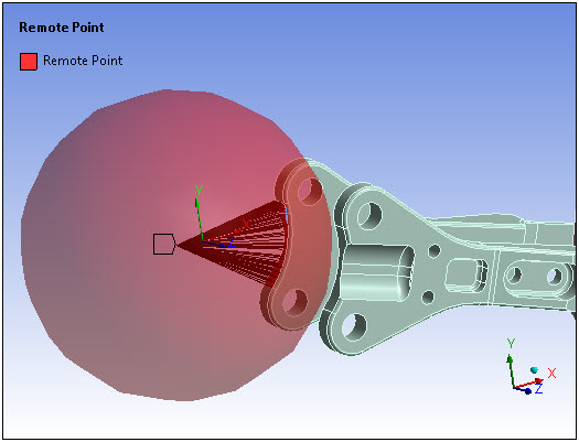
You can visualize the connection between the underlying geometry associated with a remote point and the remote point itself using the Remote Point Connections option of the Style group on the Display tab.
Once you have generated the mesh, the connection lines are drawn between the remote point and the nodes on the corresponding mesh of the underlying geometry. The connection lines take the Pinball radius into account, and only those nodes that are inside that radius will be connected with the remote point. Any remote loads that have been promoted to reference remote points will have these lines drawn when their object is selected as well. An example of connection lines is shown below.
See the Viewing and Exporting Finite Element Connections topic in the Solution Information Object section of the Help for additional information about the ability to view and work with connection lines.
Promote Remote Points
The Promote Remote Point feature is a contextual menu option that enables you to generate Remote Point objects from existing, and currently defined, boundary conditions and connection features.
Important: The promotion action changes the scoping of the corresponding object and may, as a result, cause up-to-date states to become obsolete. Promoted objects associated with a completed solution would cause the solution to become obsolete and require it to be re-solved.
Note: Automatic Remote Point promotion is available in Harmonic Response or Transient Structural analyses that use a linked Modal system to implement the Mode Superposition (MSUP) solver method for the Remote Force and Moment loads. To use this feature:
Select a supported topology (geometric or mesh entity) on your model, and
Insert a Remote Force or a Moment load.
The application automatically creates (promotes) a corresponding Remote Point for the specified load and scopes the load to that Remote Point. Automatic Remote Point creation improves processing performance by eliminating the need to create internal elements for the load.
The following objects provide the Promote Remote Point option:
To create a remote point by promotion:
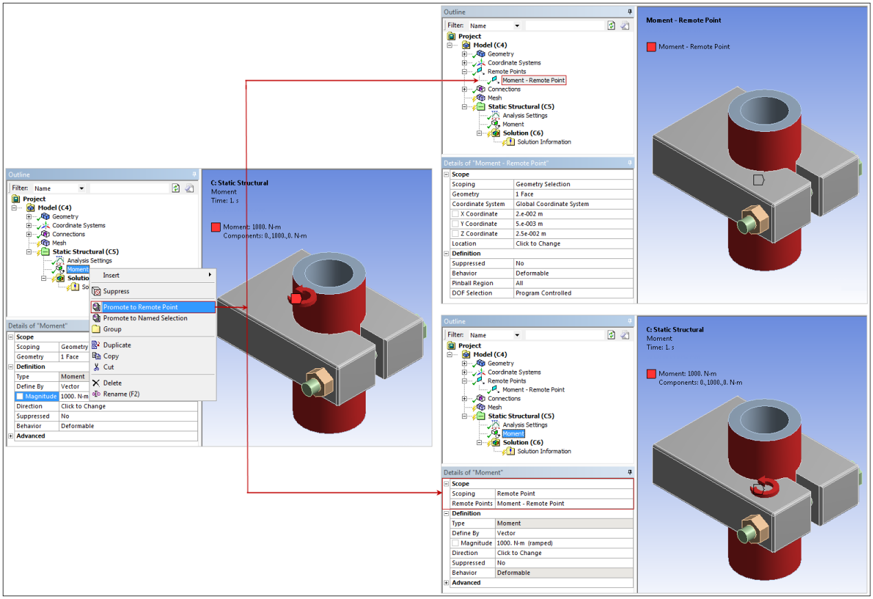
Select the object you wish to use to generate a new Remote Point, right-click, and select Promote Remote Point. The application adds a new Remote Point object to the tree. This new object contains the same scoping as the object used for promotion.
In addition and as illustrated in the example shown below, it is important to note that the scoping of the source object, the object used to generate the promotion, also changes. The application automatically updates the properties of the Scoping category of the source object and specifies the scoping to the new Remote Point. Furthermore, multiple Remote Point object can be generated based on the scoping of the source object, such as a Body-To-Body Spring.
As necessary, you can modify the specifications of the new object.
Note: This option is not available for objects scoped as a Direct Attachment, such as Springs, Joints, Beams, a Point Mass, or a Thermal Point Mass.
Program Remote Points with Commands Objects
A Commands object can be placed in the tree as a child object of a Remote Point providing you programmable access to the Remote Point pilot node. This is useful if you wish to apply conditions to the Remote Point that are not supported in Mechanical, such as beam or constraint equations.