


A spring is an elastic element that is used to store mechanical energy and which retains its original shape after a force is removed. Springs are typically defined in a stress free or "unloaded" state. This means that no longitudinal loading conditions exist unless preloading is specified (see below). In Mechanical, the feature is used to modify a Joint. If you configure a joint that has an attached spring, the spring must be redrawn in the Geometry window. In effect, the spring before the Configure action is replaced by a new spring in a new unloaded state.
Springs are defined as longitudinal and they connect two bodies together or connect a body to ground. Longitudinal springs generate a force that depends on linear displacement. Longitudinal springs can be used as a damping force, which is a function of velocity or angular velocity, respectively. Springs can also be defined directly on a Revolute Joint or a Cylindrical Joint.
The following topics are discussed in this section:
Applying Springs
To apply a spring:
After importing the model, highlight the Model object in the tree and choose the option from the Context tab.
Highlight the new Connections object, open the Spring drop-down menu and select either or from the Context tab.
Note: You can pre-select a vertex or node (Body-Ground) or two vertices or nodes () and then insert a Spring to automatically create a directly attached spring. See the Scoping subsection below.
Highlight the new object and enter information in the Details view. Note that Longitudinal Damping is applicable only to transient analyses.
Note:
The length of the spring connection must be greater than 0.0 with a tolerance of 1e-8 mm.
The Body Views display is the default display.
Remote Connection Display
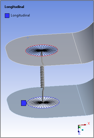
When defined as a , springs are considered to be a remote boundary condition, and can make use of remote points that were either specifically defined or created internally by the application. To do a visual check, you can display the connection lines between your scoping and the remote point by selecting the Remote Point Connections option of the Style group (Display tab). An example is illustrated here of a spring scoped to two edges.
Spring Behavior
The Spring Behavior property is modifiable for a Rigid Dynamics and Explicit Dynamics analyses only. For all other analysis types, this field is read-only and displays as Both.
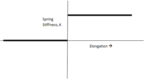
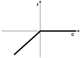
You can define a longitudinal spring to support only tension loads or only compression loads using the Spring Behavior property. You can set this property to Both, Compression Only or Tension Only. The tension only spring does not provide any restoring force against compression loads. The compression only spring does not provide resistance against tensile loads. The stiffness of a compression only or tension only spring without any preloads is shown below.
Stiffness Behavior of a Tension Only Spring:
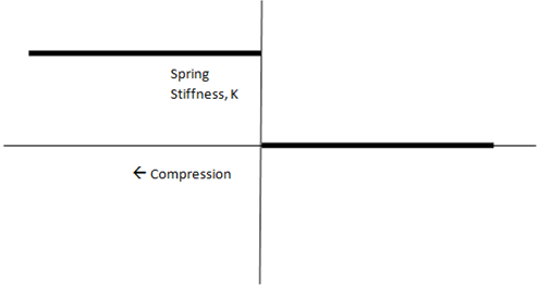
Stiffness Behavior of a Compression Only Spring:
Force Deflection Curve for a Tension Only Spring:
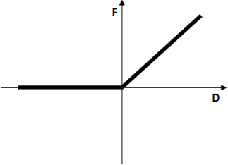
Force Deflection Curve for a Compression Only Spring:
Note: For the and options, the application uses the element LINK180. As a result, the force deflection curve will be nonlinear.
Nonlinear Spring Stiffness
A nonlinear force-deflection curve can be used to simulate multi-rate springs with nonlinear spring stiffness. A linear piecewise curve is used for this purpose.
Note that spring deflection is computed using the distance between the two ends of the spring, minus the initial length. The distance between the two points is never negative, but the deflection can be negative. If you determine that a spring exists with an incorrectly defined nonlinear stiffness, the force-deflection curve may be incorrectly defined as a result of the tabular input for nonlinear stiffness for one or more spring objects. See the details in COMBIN39 element description for more information.
Note: Support Requirements
Tabular Data requires at least two rows of data.
The properties Longitudinal Damping and Preload are not applicable for Springs with nonlinear stiffness.
For the Mechanical APDL solver, the number of data points used to define the force-deflection curve cannot exceed
20.
Points to consider for Rigid Dynamics or Explicit Dynamics analyses only:
If a nonlinear stiffness curve is defined with the Tension Only option, all points with a negative displacement are ignored.
If a nonlinear stiffness curve is defined with the Compression Only option, all points with a positive displacement are ignored.
To define a nonlinear force-deflection curve:
In the Spring object Details view settings, click in the Longitudinal Stiffness property.
Click the arrow in the Longitudinal Stiffness property then select .
Enter displacement and force values in the Tabular Data window. A graph showing force vs. displacement is displayed.
Preloading
(Not supported for Explicit Dynamics analyses.)
Mechanical also provides you with the option to preload a spring and create an initial "loaded" state. The Preload property in the Details view allows you to define a preload as a length using or to specify a specific . The actual length is calculated using spring end points from the Reference and Mobile scoping. For rigid dynamics analyses, the spring will be under tension or compression depending upon whether you specified the free length as smaller or greater than the spring length, respectively. If preload is specified in terms of , a positive value creates tension and a negative value creates compression. When the spring is linear (defined by a constant stiffness) the Rigid Dynamics solver deduces the spring free length by subtracting the value L=F/K (where F is the preload and K is the stiffness) from the actual spring length. Note that this offset is also applied to the elongation results. When the spring is non-linear (defined by a force/displacement table), this offset is not taken into account.
Spring Length
The read-only property Spring Length displays the actual length of the spring which is calculated using the end points from the Reference and Mobile scoping.
Scoping
You select the of springs as body-to-body or body-to-ground using the property of the Scope category and you define a spring’s end points using the properties of the Reference and Mobile categories. For body-to-ground property specification, the Reference is assumed to be grounded (fixed); scoping is only available on the Mobile side. Since this is a unidirectional spring, these two locations determine the spring’s line of action and as such the spring’s reference and mobile locations cannot be the same as this would result in a spring with zero length.
In addition, the Reference and Mobile categories provide the scoping property Applied By. This property enables you to specify the connection as either a Direct Attachment or a Remote Attachment. The Remote Attachment option (default) uses a Remote Point as a scoping mechanism. The Direct Attachment option enables you to scope directly to a single vertex or a node of the model.
Note: If specified as a Remote Attachment, springs are classified as remote boundary conditions. Refer to the Remote Boundary Conditions section for a listing of all remote boundary conditions and their characteristics.
You can scope of a spring to a:
Single face or to multiple faces (applied as a Remote Attachment only).
Single edge or multiple edges (applied as a Remote Attachment only).
Single vertex (can be applied as either a Remote Attachment or as a Direct Attachment) or multiple vertices (applied as a Remote Attachment only).
Single node (applied as a Direct Attachment only).
See the Spring Object Reference page of the Help for additional information about the available categories and properties.
Advanced Features
If specified as a Remote Attachment, the Reference and Mobile groups for Springs each include the following advanced properties:
Behavior: This property enables you to specify the scoped geometry as either Rigid, Deformable, or . Refer to the Geometry Behaviors section for more information.
Pinball Region: The Pinball Region is a radius value (length unit) that defines a region for selecting elements to be used by the solver for the Spring's Reference (Body-Body only) and Mobile scoping.
Material: Select your material from the fly-out menu. Your material must include a constant damping coefficient to account for viscous damping or structural damping of the Spring in the analysis. The default setting is .
Note:
The Behavior setting is applicable to underlying bodies that are flexible.
If the Scope Method property of the Spring is set to , the Spring will then assume the Behavior defined in the referenced Remote Point as well as other related properties.
When you specify a Material for the spring that includes a constant damping coefficient, based on the analysis type, the application applies damping as structural damping for damped Modal and Full Harmonic Response systems and as viscous damping for MSUP systems.
Output
Several outputs are available via a spring probe.
Example: Longitudinal Spring with Damping
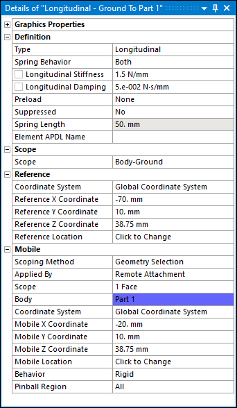
This example shows the effect of a longitudinal spring connecting a rectangular bar to ground to represent a damper. A Transient Structural analysis was performed in the environment shown:

The following are the Details pane settings of the Spring object:
Presented below is the Total Deformation result:
The following demo is presented as an animated GIF. View online if you are reading the PDF version of the help. Interface names and other components shown in the demo may differ from those in the released product.
Spring Incompatibility
(applicable only to rigid dynamics analyses)
If the preload for a longitudinal spring is a tensile load, then the spring cannot be defined as compression only. Alternatively, if the preload is a compressive load, then the spring cannot be defined as tension only. Should this case occur, the spring will be marked as underdefined and if you attempt to solve such a case, the following error message is displayed: "The preload for a spring is incompatible with its behavior being tension only spring or compression only spring."