


Overview
For Transient Thermal analyses, you can idealize the thermal capacitance of a body using a thermal point mass. Thermal Capacitance replaces the need to calculate the body's internal thermal gradient. The Thermal Point Mass is commonly used as a medium to store or draw heat from surrounding objects. Applications include the heat dissipation of refrigerators, cooling electronic devices, and heat sinks of computer motherboards.
This section examines the following feature applications and requirements:
Application
To define a Thermal Point Mass in your Transient Thermal analysis:
Select the Geometry object (or a child object).
You can then add a Thermal Point Mass object by:
Select the Geometry object and click Thermal Point option from the Mass group on the Geometry Context tab.
or...
Right-clicking the mouse and selecting > .
or...
Select the desired geometry in the graphics window, right-click the mouse, and then select > .
Specify the Scoping Method property as either , , or . Based on the selection made in this step, select a:
face, edge, or vertex of a solid or surface model or on an edge or vertex of a surface model and click Apply in the Details view for the Geometry property.
or...
single node and click Apply in the Details view for the Geometry property. In order to select an individual node, you need to first generate a mesh on the model, and then select the Node filter on the Graphics Toolbar.
or...
user-defined node-based named selection from the drop-down list of the Named Selection property.
or...
user-defined remote point from the drop-down list of the Remote Point property.
Specify the Thermal Point Mass as a (default) or a using the Applied By property. The option uses either a user-defined or a system-generated as a scoping mechanism. is the required Applied By property setting if the geometry scoping is to a single face or multiple faces, a single edge or multiple edges, or multiple vertices. The option allows you to scope directly to a single vertex (Geometry) or a node (using an individually selected node or a node-based Named Selection) of the model.
Note: The location of the Thermal Point Mass can be anywhere in space. The default location is at the centroid of the geometry.
Modify coordinate system properties as needed.
Enter a Thermal Capacitance value. Thermal Capacitance refers to ability of the material to store heat. The higher the thermal capacitance, the more heat can be stored for each degree rise in temperature of the Thermal Point Mass.
When the Thermal Point Mass is defined as a , the Behavior property displays: define as , , or . See the Behavior Property Specifications topic below for additional information about how to make the appropriate selection.
Modify additional Thermal Point Mass object Details view properties as needed.
When defined as a Remote Attachment, the Thermal Point Mass is considered a remote boundary condition. It can make use of remote points that are either specifically defined or created internally by the application. As a visual check, you can display connection lines between your scoping and remote points by selecting the Remote Point Connections option of the Style group (Display tab).
Behavior Property Specifications
The Thermal Point Mass includes three Behavior options in the Details View that control its interaction with the bodies in the geometry selection: , , and :
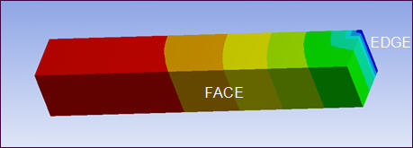
For the Isothermal behavior, temperatures throughout the geometry selections and the Thermal Point Mass are constrained to be the same. The following is an example of a Thermal Point Mass using Isothermal behavior applied to the FACE while a temperature boundary condition is located at the EDGE. While there is a temperature distribution from the boundary condition (EDGE) up to the surface (FACE), the temperature on the FACE in the pinball region, itself takes a single value that matches that of the Thermal Point Mass.

For Heat-Flux Distributed behavior, however, the temperature of the geometry selection and the point mass are not constrained to be the same. The temperature of the Thermal Point Mass becomes a weighted average of those on the geometry selection. For comparison, the previous example has been modified to use the Heat-Flux Distributed behavior. The FACE, no longer constrained to be isothermal to the point mass, displays a gradient.
For Coupled behavior, the geometry has the same DOF solution on its underlying nodes as the remote point location. This formulation is similar to the Mechanical APDL constraint defined by the CP command.
Support Limitations
A Thermal Point Mass cannot be applied to a vertex scoped to an end release.