


Use the Analyses Selection feature to specify whether to apply specific objects to one or more analyses included in your simulation. Only environments that use the Mechanical APDL solver and that are independent (no initial conditions) from other environments can use this feature. That is, this feature will not present environments in the worksheet if there is an upstream system that provides initial conditions to a downstream environment. For instance, this feature does not support structural optimization analyses because they depend on an upstream system. Unsupported analysis systems display in the worksheet with a Not Applicable (NA) label.
Go to a section topic:
Supported Objects
The Analyses Selection feature supports the following folders/objects:
Boundary Conditions folder (Bolt Pretension loads only)
Connections folder:
Contacts Folder > Contact Region objects.
Joints Folder > Joint objects.
Materials object and Material Assignment objects.
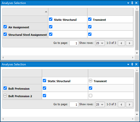
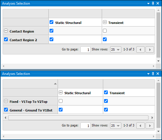
As illustrated, for each supported object, the pane provides a worksheet of all environments and associated boundary condition, connection, joint, or material assignment objects specified in the simulation.
 |
 |
Using the Worksheet
For the supported objects, make Analyses Selection pane selections as follows:
The analysis type row and the object column each automatically select either all objects or all analysis types.
Selecting an individual object’s cell selects the object for the corresponding analysis. You can make multiple selections in these individual cells. Note that partial selections
Based your selections, the application writes the data for the object(s) to the ds.dat file.
By default, when you display the pane, the application automatically selects all check boxes.
For these "partial selections," the icon in the column or row changes to indicate a
partial selection  .
.
If you specify more than one Material Assignment object to the same part or body, the last assignment object created takes precedence when the application creates the ds.dat file.
Note: Objects displayed in the pane must be applicable to the analysis types specified in your simulation. You can include a Bolt Pretension load in a thermal analysis, but the Analyses Selection pane will not write data for this object to the input file because it is not supported by the analysis type.
Specifying Global Bolt Pretension Loads
You commonly add a Bolt Pretension loading condition to an environment of your simulation. You can also insert a Bolt Pretension load from the Boundary Conditions folder. This optional folder is first inserted from the Model object of your simulation. Currently, Bolt Pretension is the only boundary condition available from the Boundary Conditions folder.
You can insert the boundary condition directly at the model-level or you can create it under the analysis environment and promote the object.
- From the Model Object
Select the Model object.
From the Model Context tab, open the Boundary Conditions option and select . Alternatively, right-click the Model object or within the Geometry window, and select Insert > Boundary Conditions > Bolt Pretension.
Specify the properties of the boundary condition.
- From the Environment Object
Select the Environment object.
From the Environment Context tab: open the Loads drop-down menu and select Bolt Pretension. Alternatively, right-click the Environment object or within the Geometry window, and select > .
Specify the properties of the boundary condition.
Right-click the Bolt Pretension object and select . This automatically inserts the boundary condition under the Model object.
Important: The Boundary Conditions object includes one Details pane property: Number of Steps. This property defines the number of initial loads steps for any Bolt Pretension load specified in the group. The default setting is
1. Once you define a load, use the Tabular Data window to modify these load steps. The Number of Steps property of the Boundary Conditions object only specifies the number of steps when you create the load. Any change to the setting of the Number of Steps property only affects subsequent loads you create.Highlight the Boundary Conditions object and select the Analyses Selection option from the Boundary Conditions tab. The worksheet displays all of the environments and model-level boundary conditions available in the simulation. Select the check box beside each analysis system to apply the boundary condition.
Limitations
Note the following:
The following analysis systems do not support the use of contacts, joints, or Material Assignment in the Analyses Selection worksheet:
Explicit Dynamics
Motion
Rigid Dynamics
Structural Optimization
The Analyses Selection worksheet does not support the following joint types:
Point on Curve Joint
In-Plane Radial Gap (Imperfect)
Spherical Gap (Imperfect)
Radial Gap (Imperfect)
Screw
Constant Velocity (Homokinetic)
Distance
Models that include a large number of Contacts, Joints, or Material Assignment objects may require additional time to display in the Analysis Selection worksheet.
The application does not process inactive Contact Regions in the worksheet for the associated environment, however, they can still be used by certain Mesh Edit features that require a Contact Region.
You need to make sure that you fully define all objects, even if they are not enabled for a solution on the Analyses Selection worksheet. Underdefined objects may prevent you from running the solution.