


A bearing is a two-dimensional elastic element used to confine relative motion and rotation of a rotating machinery part. Bearings are a critical support for Rotordynamics analyses and as such, a good bearing design is essential to ensure stability of machinery parts under high speed rotations.
Similar to a spring, a bearing has the structural characteristics of longitudinal stiffness and damping. In addition to these characteristics, bearings are enhanced with coupling stiffness and damping that serve as resistive forces to movement of the machinery part in a rotation plane.
Bearings are supported by all Mechanical analysis types that use the Mechanical APDL solver.
Note:
The damping characteristics are not applicable to Static Structural, Eigenvalue Buckling, undamped Modal, and Response Spectrum analysis systems.
While negative stiffness and/or damping characteristics are allowed in all the supported analysis systems, users are cautioned to ensure its proper use, and check the results carefully.
This boundary condition cannot be applied to a vertex scoped to an End Release.
Scoping Requirements
Bearing scoping is limited to a single face, single edge, single vertex, or an external remote point. Similar to a spring, there is a Mobile side and Reference side for the bearing connection. Based on the Mobile and Reference side selections, a bearing can be made as a bearing connection between Body to Ground or Body to Body.
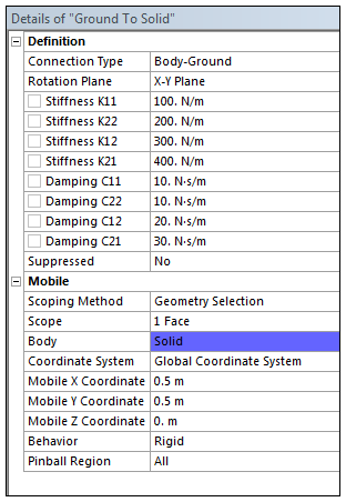
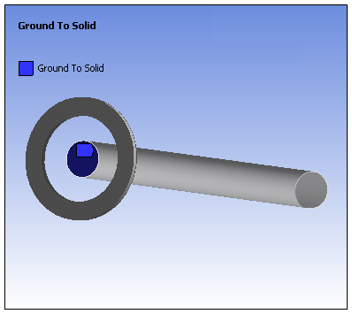
- Body to Ground Bearing
When specifying the Connection Type property as , the reference side is assumed to be grounded (or fixed) and the mobile side is set to the scoped entity. Unlike Body-Ground springs, the location of the reference side is set to that of the mobile side because they can be coincident during a linear analysis.
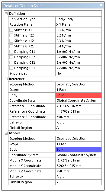
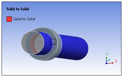
- Body to Body Bearing
When specifying the Connection Type property as , both the reference and mobile sides can be set to the scoped geometric entities. Scoped entities of Mobile and Reference should be on two different bodies and the Reference and Mobile locations should be in a selected rotation plane.
For more information about the use of a spring-damper bearing, see COMBI214 - 2D Spring-Damper Bearing in the Mechanical APDL Theory Reference.
Apply Bearing
To add a Bearing:
Add a Connections folder if one is not already in the tree, by highlighting the Model object and choosing from the Model Context Tab or by choosing > from the context menu (right-click).
Add a Bearing object by selecting the Connections folder and then opening the Bearing drop-down menu and then selecting the or the option. You can also right-clicking on the Connections folder and selecting > from the context menu. This method specifies the Connection Type property as by default.
Under the Definition category, specify the Rotation Plane property for your model. Selections include:
(default)
As required, define the stiffness coefficients (K11, K22, K12, K21) and the damping coefficients (C11, C12, C21, C22). These may be entered as Constant values or using Tabular Data entries.
If you are defining your stiffness and damping coefficients as Tabular Data, they are dependent upon Rotational Velocity (as provided in the first column of the Tabular Data window).
In addition, when Rotational Velocity-dependent bearings are used for Modal and Full Harmonic Response analyses, the Coriolis Effect property (Analysis Settings>Rotordynamics) must be set to .
The application uses interpolated bearing properties for each Rotational Velocity defined in Modal or Full Harmonic Response analyses. When there is no Rotational Velocity defined in the system, the first entry of Bearing properties is used.
See COMBI214 - 2D Spring-Damper Bearing in the Mechanical APDL Theory Reference for additional information as well as the example shown below.
Specify the following properties under the Reference and Mobile categories of the Body-Body Bearing and Mobile group of Body-Ground bearing.
Specify a Coordinate System. This property provides a drop-down list of available coordinate systems. Global Coordinate System is the default.
Define the Scoping Method as Geometry Selection (default) or Named Selection. The Scoping Method may also be specified to a user-defined Remote Point, if available.
Specify the Connection Behavior as either Rigid (default), Deformable, or . If the Scope Method property of the Bearing is set to , the Bearing will then assume the Behavior defined in the referenced Remote Point as well as other related properties. The Behavior formulation is not supported for Bearings.
As needed, specify a Pinball Region. Use the Pinball Region to define where the bearing attaches to face(s) or edge(s) if the default location is not desirable. By default, the entire face/edge is tied to the bearing element. In the event that this is not desirable, you can choose to enter a Pinball Region value. For example, your topology could have a large number of nodes leading to solution processing inefficiencies. Or, if there is overlap between the bearing's scoped faces and another displacement boundary condition, you could experience over-constraint and possible solver failure.
Note:
The Pinball Region and Behavior settings are applicable to underlying bodies that are flexible.
The Pinball Region and Behavior settings are not applicable to a Bearing scoped to the vertex of line body.
\Because a Bearing is a remote boundary condition, it can make use of remote points that were either specifically defined or created internally by the application. As a visual check, you can display connection lines between your scoping and the remote point by selecting the Remote Point Connections option of the Style group (Display tab).
The following examples illustrates Bearings for Body-Ground or Body-Body with customized Details settings.
- Body-Ground
- Body-Body
The stiffness characteristics K11, K22, K12, and K21, and damping characteristics C11, C22, C12, and C21 are used to model four spring-damper sets in a plane of a rotating shaft in this example. For more information about the spring-damper orientation, see COMBI214 - 2D Spring-Damper Bearing in the Mechanical APDL Theory Reference.
The bearing is created on a face of the shaft that is perpendicular to the Z-axis. As the Z-axis is the rotating axis of the shaft, the X-Y Plane is selected for the Rotation Plane option. While the bearing in this example is defined using Global Coordinate System, it can also be defined with a user-defined local coordinate system. When changing from one coordinate system to another, the Bearing needs the scoping to be updated to desired location for the new coordinate system.
For a bearing to be modeled properly, the location of the reference side and the mobile side must lie in the selected rotation plane.