


The Annotation Preferences dialog box controls the visibility of all annotations, such as custom annotations and annotation labels, annotations on objects such as cracks, point masses, and springs.
To set your annotation preferences:
Click the Preferences option in the Annotation group on the Display tab.
The Annotation Preferences dialog box appears. By default, all annotations are selected, and therefore set to visible.
Under Basic Annotations, select or clear the check boxes for the following options:
View Annotations: Toggles the visibility of annotations in the Geometry window.
View User Defined Graphics Annotations: Toggles the visibility of custom user annotation in the Geometry window.
View Annotation Labels: Toggles the visibility of annotation labels in the Geometry window.
Under Remote Boundary Conditions, select or clear the check boxes for the following options:
Point Masses: Toggles the visibility of annotations for point masses.
Springs: Toggles the visibility of annotations for springs.
Beam Connections: Toggles the visibility of annotations for beam connections.
Bearings: Toggles the visibility of annotations for bearings.
Note: The size range for Point Masses and Springs is from 0.2-2 (Small-0.2, Default-1, Large-2).
Under Remote Boundary Conditions, slide the indicator to specify the size of the annotations for Point Masses and Springs.
Under Additional Display Preferences, select or clear the check boxes for the following options:
Crack Annotations: Toggles the visibility of annotations on crack objects.
Individual Force Arrows on Surface Reactions: Toggles the visibility of individual force arrows on surface reactions.
Body Scoping Annotations: Toggles the visibility of annotations on body scoping.
Under Mesh Display, select or clear the check boxes for the following options:
Mesh Annotations: Toggles the visibility of mesh node and mesh element annotations in Named Selection displays.
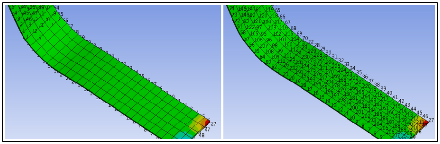
Node Numbers: Toggles the visibility of mesh node numbers in Named Selection, Mesh, and Result displays. This selection also provides options to specify a numerical range of which nodes to display. For example, display the nodes
1(Min) through200(Max). An increment (Inc) property enables you to further define the range so that it selects only every Nth value (for example, every 5th node). The default Minimum value is1and the default Maximum value is100000.Depending upon the number of nodes that you are displaying as well as how you have positioned your model in the Geometry window, Node Numbers may not fully display, as illustrated below. The Rescale Annotation option, available in the Graphics Toolbar, adjusts the size of annotation symbols, as such, this option may improve the display issue.
Element Numbers: Toggles the visibility of mesh element numbers in Named Selection, Mesh, and Result displays. This selection also provides options to specify a numerical range of which elements to display. Because Element Numbers are displayed at the centroid of the elements, Wireframe mode is required to properly display all Element Numbers.
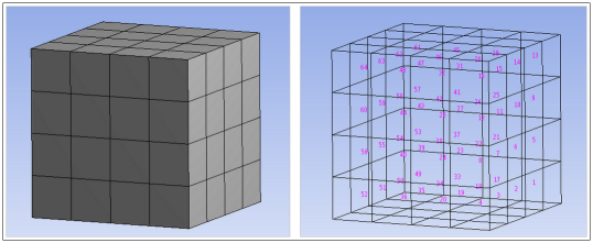
Plot Elements Attached to Named Selections: Toggles the visibility of elements for all items in the Named Selections group. For nodal Named Selections, this option shows the full elements, while for face or body Named Selections this option shows just the element faces. This option does not affect Line Bodies. You must have the Show Mesh button toggled off to see the elements in the Named Selection.
When you are finished specifying your annotation preferences, click Apply Changes to apply your preferences and leave the dialog box open, or click OK to apply and close.