|
Definition
|
-
Connection Type
The Connection Type property
specifies the joint as either a
scoping (multiple
faces) or a Body-Ground scoping
(multiple faces). When defined as
, you need to define
Reference category and
Mobile category properties. When
you specify the Connection Type as
body-to-ground, the application assumes that the reference
element of the joint is grounded (fixed). -
Type
The Type property provides a
drop-down list of joint type options. See the Specifying Remote Points section for descriptions
of each type.
Note: The General
joint enables you to specify each degree of freedom as
being either Fixed or
Free.
- Formulation
You use this property to specify a desired element type
for the Bushing Joint. The options for this property include
(Multi-Point Constraint)
and . These options enable
you to specify the underlying element type for the Bushing
Joint. The option uses the
MPC184 element and the
option uses the
COMBI250 element.
Important: The option is
only supported for the following analysis types: All Substructure analyses when the
Joint as included in the
Condensed Part. Modal and Harmonic Response. Static Structural when you active Beta Options.
When you specify the
option, the Element
Coordinate System property also displays. As needed,
specify a user-defined coordinate system. The default setting
for this property is .
Important: When you set the
property to
: The Element Coordinate
System is the first coordinate system
used to apply rotation. This is followed by nodal rotations defined on
associated Remote Points
(Reference or
Mobile), such as the
NROTAT command that rotates nodal
coordinate systems into the active system. In
addition, rotations from these remote points modify
the element matrix (see the Input Data topic of the
COMBI250 element
reference). This is then followed by the normal
processing sequence for rotations. Ansys recommends that you specify the same
coordinate system for Element Coordinate
System, Reference Coordinate
System, and Mobile Coordinate
System properties in case there is a
relative rotation between the Element
Coordinate System and either the
Reference Coordinate System or
Mobile Coordinate System. In
addition, you need to verify proper rotation as well
as results.
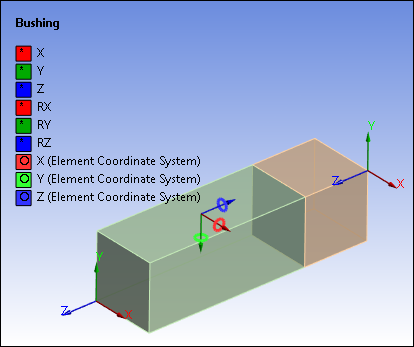
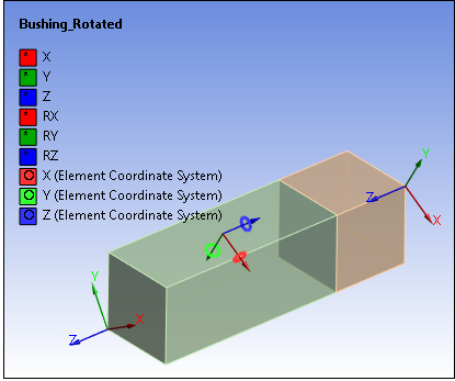
Here is an example of Element Coordinate System
annotations ("rings" about each axis),
prior to and after rotation.
- Solver Element Type (MAPDL Solver Only)
The Solver Element Type property
enables you to specify the type of element to use in a fixed
joint. Options include:
(default): When selected, an Mechanical APDL joint
element is used unless a rigid body exists in the
model.
: this
selection uses the MPC184
element. This option enables you to use the Joint
probe. In addition, this option may allow you to
experience convergence improvements if you are
attaching a shell or line body to a node or
vertex.
: this
selection uses the
TARGE170 element for
Body-Body joints and a DOF constraint for
Body-Ground joints. This option helps to avoid
solver pivoting as well as MPC
overconstraint.
-
Torsional Stiffness
The Torsional Stiffness property
defines the measure of the resistance of a shaft to a
twisting or torsional force. You can add torsional stiffness
only for cylindrical and revolute
joints. -
Torsional Damping
The Torsional
Damping property defines the measure of
resistance to the angular vibration to a shaft or body along
its axis of rotation. You can add torsional damping only for
cylindrical and revolute
joints. -
Suppressed
Includes or excludes the joint object in the
analysis. -
Element APDL Name
Element APDL Name:
Optional property that enables you to manually define an APDL
parameter (in the input file) and assign the parameter value as
the element of the Joint. This facilitates easy programmatic
identification of the element of the Joint for later
use/reference in a Commands
(APDL) object.
|
|
Reference
|
-
Scoping Method
This property enables you to choose to scope using a
(default),
, or a
user-defined .
Note: If you scope a joint to a user-defined
, it is
required that the remote point be located at the origin
(0.0, 0.0, 0.0) of the of the remote point.
- Applied By
This property specifies the joint as a (default) or a
. The
option uses
either a user-defined or a system-generated Remote
Point as a scoping mechanism.
is the
required Applied By property setting if
the geometry scoping is to a single face or multiple faces,
a single edge or multiple edges, or multiple vertices. The
option
enables you to scope directly to a single vertex (Geometry)
or a node (using an individually selected node or a
node-based Named Selection) for flexible bodies (only) on
your model. is
not allowed if scoped to solid bodies, as they do not have
rotational degrees of freedom.
Note: Direct Attachment is not allowed for the Explicit
Dynamics solver.
-
Scope (or Reference
Component or Remote
Point)
Based on the selected Scoping Method,
this property displays as either "
Scope
", "
Reference Component
", or "
Remote Points
". When is
selected as the Scoping Method, this property displays with
the label "
Scope
" and enables you to define the geometry to which the
joint is applied. Once a geometry is selected, click in the
Scope field and then click
. When is
selected as the Scoping Method, this
property provides a drop-down list of available user-defined
Named Selections. When is selected
as the Scoping Method, this property displays with the label "
Remote Points
". This property provides a drop-down list of
available user-defined Remote Points. This property is not
available when the Applied By property
is specified as . -
Body
This read-only property displays the corresponding
part/geometry name. -
Coordinate System
The scoping of a joint must be accompanied by the
definition of a joint coordinate system. This coordinate
system defines the location of the joint. It is imperative
that the joint coordinate system be fully associative
with the geometry, otherwise, the coordinate system could
move in unexpected ways when the
Configure tool is used to define
the initial position of the joint (see the Applying
Joints section). A warning message is issued if
you attempt to use the Configure tool
with a joint whose coordinate system is not fully
associative. Under the Reference category, the
Coordinate System property provides
a default Reference Coordinate System.
This coordinate system accompanies a joint when the joint is
added to the tree. This applies for joints whose
Connection Type is either
or
. When a joint is
added, an associated coordinate system is automatically
generated at a location based on the selected geometry
(face, edge, or vertex). You can modify the Reference
Coordinate System’s orientation axis by modifying the
details of the Reference Coordinate
System object contained in the joint
object. Additional information
about Modifying Joint
Coordinate Systems is also available, including
the following topics:
Scoping a joint directly to a vertex or a node using the
option
fixes the coordinate system to that location. Note that the
Reference Coordinate System
property displays automatically and is read-only. -
Behavior
For remote attachments, use the
Behavior property to specify the
scoped geometry as either Rigid,
Deformable, or
. If the Scope
Method property of the Joint is set to
, the Joint will
then assume the Behavior defined in
the referenced Remote Point as well as other related
properties. Refer to the Geometry Behaviors section for more
information. - Formulation
When the Behavior property is set to
either Rigid or
Deformable, you use this property
to specify the contact algorithm used for a particular
reference computation. If you set the Scope
Method property to Remote
Point, the Joint uses the
Formulation defined for the
Remote Point. Property options
include: (default): This
option creates multipoint constraint equations
internally during the Mechanical APDL solution to
tie the bodies together. : This option enforces
zero penetration when the contact is closed,
making use of a Lagrange multiplier on the normal
direction and a penalty method in the tangential
direction. This formulation helps to overcome
over-constraint problems better than the MPC
formulation.
For more information, see the Selecting a Contact
Algorithm (KEYOPT(2)) topic in the
Mechanical APDL Contact Technology Guide. - Relaxation Method
This property is only available when the
Formulation property is set to
. You use this property to
eliminate overconstraint present in the joint reference
condition. Property options include
(default) and
. If you set the Scope Method property to
, the joint uses
the setting of the Relaxation Method
property defined for the Remote
Point. For more information, see the Overconstraint Detection and
Elimination section of the Mechanical APDL
Contact Technology Guide. -
Pinball Region
Use the Pinball Region property to
define where the joint attaches to face(s) if the default
location is not desirable. By default, the entire face is tied to the
joint element. This may not be desirable, warranting the
input of a Pinball Region setting, for
the following reasons: If the scoping is to a topology with a large
number of nodes, this can lead to an inefficient
solution in terms of memory and speed. Overlap between the joint scoped faces and other
displacement type boundary conditions can lead to
over constraint and as a result, solver
failures.
Note:The Pinball Region,
Behavior,
Formulation, and
Relaxation Method settings
are applicable to underlying bodies that are
flexible. If a Joint’s
Reference and
Mobile category are scoped to
separate Remote
Points, the Pinball
Region,
Behavior,
Formulation, and
Relaxation Method properties
for each category become read-only and are set to
the respective remote points. The Pinball Region,
Behavior,
Formulation and
Relaxation Method properties
are not applicable when the Applied
By property is set to
.
|
|
Mobile
|
-
Scoping Method
This property enables you to choose to scope using a
(default),
, or a
user-defined .
Note: If you scope a joint to a user-defined
, it is
required that the remote point be located at the origin
(0.0, 0.0, 0.0) of the Reference Coordinate
System of the remote point.
- Applied By
This property specifies the joint as a (default) or a
. The
option uses
either a user-defined or a system-generated Remote
Point as a scoping mechanism.
is the
required Applied By property setting if
the geometry scoping is to a single face or multiple faces,
a single edge or multiple edges, or a single vertex or
multiple vertices. The option allows you to scope
directly to a single vertex (Geometry) or a node (using an
individually selected node or a node-based Named Selection)
to flexible bodies (only) on your model. Direct Attachment
is not allowed if scoped to solid bodies, as they do not
have rotational degrees of freedom.
Note: Direct Attachment is not allowed for the Explicit
Dynamics solver.
-
Scope (or Mobile
Component or Remote
Point)
Based on the selected Scoping Method,
this property displays as either "
Scope
", "
Mobile Component
", or "
Remote Points
". When is
selected as the Scoping Method, this property displays with
the label "
Scope
" and enables you to define the geometry to which the
joint is applied. Once a geometry is selected, click in the
Scope field and then click
. When is
selected as the Scoping Method,
provides a drop-down list of available user-defined Named
Selections. When is selected
as the Scoping Method, this property displays with the label "
Remote Points
". This property provides a drop-down list of
available user-defined Remote Points. This property is not
available when the Applied By property
is specified as . -
Body
This property is available under both the
Reference and
Mobile categories. This read-only
property displays the corresponding part/geometry
name. -
Coordinate System
The Mobile category provides the
support for the relative motion between the parts of a
joint. A Mobile Coordinate System is
automatically defined but is only displayed in the tree when
the property is
set to . Scoping a joint directly to a vertex or a node using the
Direct Attachment option fixes the
coordinate system to that location. When scoping directly to
a node or vertex using the Direct
Attachment option, the default setting for
the Initial Position property is
even though the
property
doesn't display in the Details. Rather, the Coordinate
System automatically displays and is read-only.
Note: For the Mechanical APDL solver, Body-Ground joints use the
Coordinate System defined on the
Mobile side if Override is
active, when scoped to a Remote Point, or when using the
Direct Attachment option.
-
Initial Position
This property applies to remote attachments only (direct
attachments fix the coordinate system). It provides a
drop-down list with the options
Unchanged and
Override. The
Unchanged option indicates the use
of the same coordinate system for the
Reference category and the
Mobile category and the
Override option causes a
Coordinate System property to
display in the Mobile category with the
default setting .
Caution: If you are scoping a joint to a Remote
Point, you cannot scope the
Initial Position setting of a
Joint's Mobile category as
Unchanged. This is also true
when the Direct Attachment
option is used because the Initial
Position property is not available
(Override is active).
-
Behavior
For remote attachments, use the
Behavior property to specify the
scoped geometry as either Rigid,
Deformable, or
. If the Scope
Method property of the Joint is set to
, the Joint will
then assume the Behavior defined in the
referenced Remote Point as well as other related properties.
Refer to the Geometry Behaviors
section for more information. - Formulation
When the Behavior property is set to
either Rigid or
Deformable, you use this property
to specify the contact algorithm used for a particular
reference computation. If you set the Scope
Method property to Remote
Point, the Joint uses the
Formulation defined for the
Remote Point. Property options
include: (default): This
option creates multipoint constraint equations
internally during the Mechanical APDL solution to
tie the bodies together. : This option enforces
zero penetration when the contact is closed,
making use of a Lagrange multiplier on the normal
direction and a penalty method in the tangential
direction. This formulation helps to overcome
over-constraint problems better than the MPC
formulation.
For more information, see the Selecting a Contact
Algorithm (KEYOPT(2)) topic in the
Mechanical APDL Contact Technology Guide. - Relaxation Method
This property is only available when the
Formulation property is set to
. You use this property to
eliminate overconstraint present in the joint mobile
condition. Property options include
(default) and
. If you set the Scope Method property to
, the joint uses
the setting of the Relaxation Method
property defined for the Remote
Point. For more information, see the Overconstraint Detection and
Elimination section of the Mechanical APDL
Contact Technology Guide. -
Pinball Region
For remote attachments, use the Pinball
Region property to define where the joint
attaches to face(s) if the default location is not
desirable. By default, the entire face is tied to the joint element.
This may not be desirable, warranting the input of a
Pinball Region setting, for the
following reasons: If the scoping is to a topology with a large
number of nodes, this can lead to an inefficient
solution in terms of memory and speed. Overlap between the joint scoped faces and
other displacement type boundary conditions can
lead to over constraint and as a result, solver
failures.
Note:The Pinball Region,
Behavior,
Formulation, and
Relaxation Method properties
are not visible when the Applied
By method is . The Pinball Region and
Behavior settings are
applicable to underlying bodies that are
flexible. If a Joint’s
Reference and
Mobile category are scoped to
separate Remote
Points, the Behavior
and Pinball
Region properties for each
category become read-only and are set to the
respective remote points.
|
|
Stops
|
See the Joint Stops and Locks section.
|