


For either Reference or Mobile joint coordinate systems, both the location and the orientation of the coordinate system can be changed as shown below.
Important: For a Bushing joint when you set the property to , the application uses the element COMBI250. As a result:
The Element Coordinate System is the first coordinate system used to apply rotation.
This is followed by nodal rotations defined on associated Remote Points (Reference or Mobile), such as the NROTAT command that rotates nodal coordinate systems into the active system. In addition, rotations from these remote points modify the element matrix (see the Joint Stiffness section as well as the COMBI250 Input Data topic in the COMBI250 section of the Mechanical APDL Element Reference).
In addition, rotations from these remote points modify the element matrix (see the Joint Stiffness section as well as the Input Data topic of the COMBI250 element reference).
Ansys recommends that you specify the same coordinate system for Element Coordinate System, Reference Coordinate System, and Mobile Coordinate System properties in case there is a relative rotation between the Element Coordinate System and either the Reference Coordinate System or Mobile Coordinate System. In addition, you need to verify proper rotation as well as results.
This is then followed by the normal processing sequence for rotations.
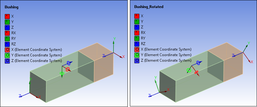
Here is an example of Element Coordinate System annotations ("rings" about each axis), prior to and after rotation.
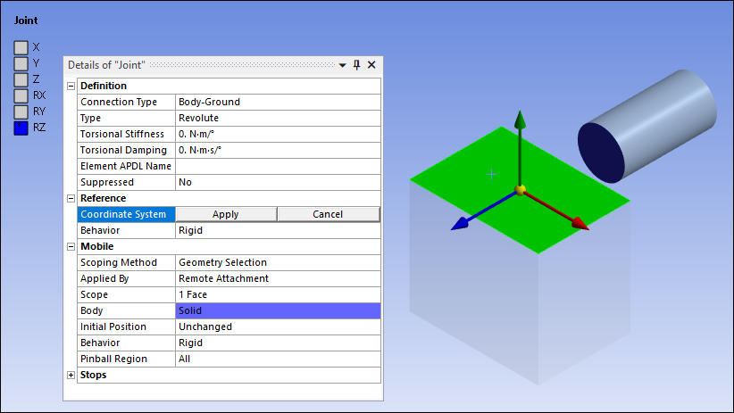
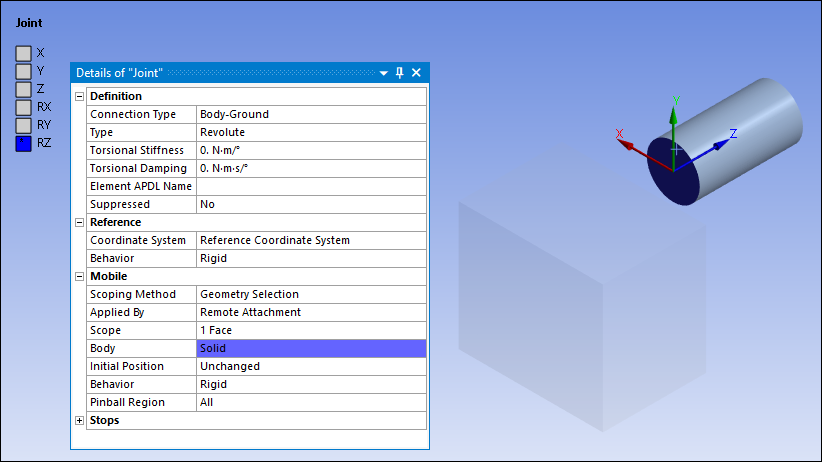
To move a joint coordinate system to a particular face:
Highlight the Coordinate System field in the Details view of the Joint object. The origin of the coordinate system will include a yellow sphere indicating that the movement "mode" is active.

Select the face that is to be the destination of the coordinate system. The coordinate system in movement mode relocates to the centroid of the selected face.
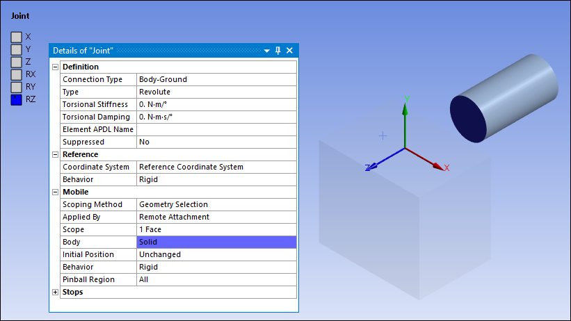
Click the Apply button. The image of the coordinate system changes from movement mode to a permanent presence at the new location.
To change the orientation of a joint coordinate system:
Highlight the Coordinate System field in the Details view of the Joint object. The origin of the coordinate system will include a yellow sphere indicating that the movement "mode" is active.
Select any of the axis arrows you wish to change. Additional "handles" are displayed for each axis.

Select the handle or axis representing the new direction to which you want to reorient the initially selected axis.
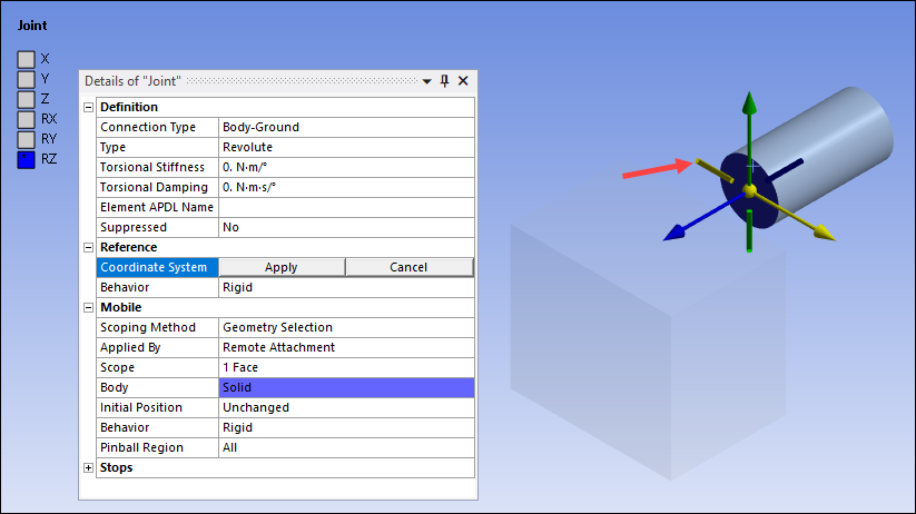
The axis performs a flip transformation.

Click the Apply button. The image of the coordinate system changes from movement mode to a permanent presence at the new orientation.
You can change or delete the status of the flip transformation by highlighting the Reference Coordinate System object or a Mobile Coordinate System object and making the change or deletion under the Transformations category in the Details pane of the child joint coordinate system.
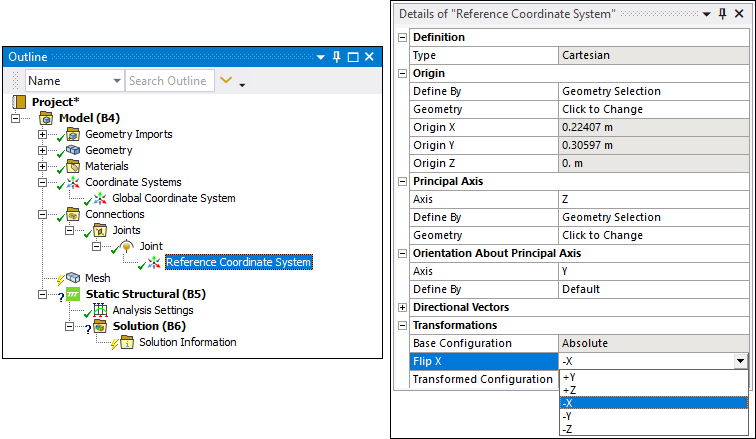
When selecting either a Reference Coordinate System object or a Mobile Coordinate System object, various settings are displayed in the Details view. These are the same settings that apply to all coordinate systems, not just those associated with joints. See the following section on coordinate systems: Initial Creation and Definition for an explanation of these settings.