


To specify a Remote Point:
Select the Model object and then select the Remote Point option from the Model Context tab.
Or, you can right-click and select > .
Specify the scoping. Options include (default), , , Remote Points and Nodes, or . See the descriptions below.
Note:
To select nodes, you first need to generate the mesh.
This scoping option is not supported for the LSDYNA Solver.
Mechanical APDL Reference
When you scope your Remote Point to a single node or multiple nodes, a point-to-surface contact algorithm is used (using contact element CONTA175). This process can produce a slightly different result at the area of application compared to face scoping of the same topology. Geometry scoping to 3D faces and 2D edges uses a constant traction contact application (contact elements CONTA171 through CONTA174). However, a Remote Point scoped to one or more vertices of a 2D or a 3D solid does not use MPC-based contact. Instead, beam elements are created by the solver to connect the vertex to the Remote Point. Furthermore, when scoped to the vertex of a line body, the application uses the element TARGE170 in (rigid) line form.
Important: For systems solved using the Mechanical APDL solver:
When a Remote Point is scoped to a single node, the remote attachment may be rotationally unconstrained if the:
Behavior property of the remote point is set to .
Or...
The scoped node does not have rotational DOFs, such as nodes included in solid body or a 2D surface body.
When a Remote Point is scoped to multiple nodes that are collinear, the rotations along the line of collinear nodes may not transfer if the scoped nodes belong to solid bodies because the nodes on a solid body do not have rotational DOFs.
Also note that this limitation applies to objects that use remote points, such as Moments.
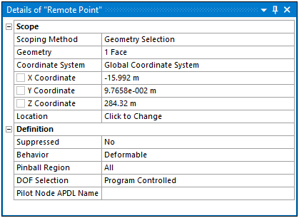
Details Properties
Remote Point definable properties are listed and described below:
Scoping Method: Options include (default), , , Remote Points and Nodes, or .
Note: When you specify , the Geometry, Pinball Region, Behavior, and DOF Selection properties do not appear in the Details. Free Standing Remote Points can be used to model structures such as Tuned Mass Dampers by directly connecting pieces of your model together.
Geometry/Named Selection (geometry or node-based) selection. These options support face, edge, vertex, node, or element face selection/specification.
Outline Selection: When you specify Remote Point or Remote Points and Nodes as the Scoping Method, this property displays. It is scoped to an existing Remote Point.
Select the entry field of the property and then select the desired Remote Point objects from the Outline.
Click the Apply button that displays automatically. Once specified, this field displays the number of Remote Point objects you have selected (for example, , , etc.).
Note: During Transient Thermal analyses, an error condition could arise for a Remote Point scoped to multiple Remote Point objects.
Nodes: When you specify Remote Points and Nodes as the Scoping Method, this property displays. This option enables you perform direct node selection for the Remote Point in addition to the scoping of one or more Remote Point objects.
Coordinate System: the Coordinate System based on the original location of the remote point. This property does not change if you modify the remote point's position with the Location property.
Note: When you scope a Remote Point to a load or a result (Scoping Method property is set to ), the direction used to calculate the load or to evaluate the result is based on the Coordinate System property of the Remote Point object. This also applies to when Remote Points like this are used with a Commands (APDL) object.
X Coordinate: the distance from the coordinate system origin on the x axis.
Y Coordinate: the distance from the coordinate system origin on the y axis.
Z Coordinate: the distance from the coordinate system origin on the z axis.
Location: the location in space of the remote point. This property enables you to manually modify the remote point’s original position. Changing the property re-plots the x, y, and z coordinate locations, but does not establish a new coordinate system, reflected by the Coordinate System property.
For a remote point, use this property to define the remote point's position in space.
Important: When you first scope a Remote Point and you do not also define the Location property, the application sets the position of the remote point to the centroid of the scoped geometry selection(s) or if scoped to multiple Remote Points, the centroid of those Remote Points. Any subsequent scoping changes will not change this position. You must update the Remote Point's location as needed.
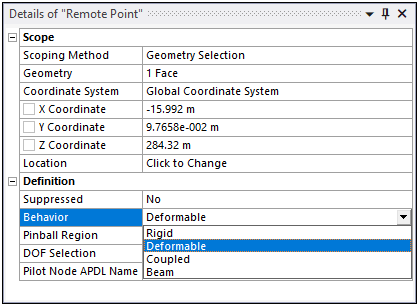
Behavior. Specify the behavior of the connection of the Remote Point to the model. Options include , , , or .
Formulation: This property enables you to specify the contact algorithm the application uses for a particular remote point computation. Property options include:
(default): This option creates multipoint constraint equations internally during the Mechanical APDL solution to tie the bodies together.
: This option enforces zero penetration when the contact is closed, making use of a Lagrange multiplier on the normal direction and a penalty method in the tangential direction. This formulation helps to overcome over-constraint problems better than the MPC formulation.
Note:
The Formulation property is not supported when the Behavior property is set to .
The option is not supported when the Behavior property is set to .
The option is not supported when you deactivate any DOF for target elements using the DOF Selection property (KEYOPT(4)).
For more information, see the Selecting a Contact Algorithm (KEYOPT(2)) topic in the Mechanical APDL Contact Technology Guide.
Relaxation Method: This property is only available when the Formulation property is set to . Property options include (default) and . Setting this property to eliminates overconstraints. When MPC-based surfaced-based constraints or rigid bodies are subjected to overconstraint, this method relaxes the constraint between contact-generated internal constraint equations and other constraint equations or Lagrange multipliers.
For more information, see the Overconstraint Detection and Elimination section of the Mechanical APDL Contact Technology Guide.
Pinball Region: The Pinball Region for a Remote Point is a radius value (length unit) that defines a region for selecting elements to be used by the solver for the Remote Point's scoping.
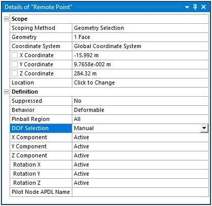
DOF Selection: Options include Program Controlled (default) or Manual. This offers an opportunity for better control of which DOF's will activate for corresponding constraint equations. If you specify Manual for DOF Selection in an Explicit Dynamics system, the active/inactive settings of the X, Y, and Z Components and the X, Y, and Z Rotations are ignored, because these settings do not play a role in the constraint equations for an Explicit Dynamics system.
Important: When the Behavior property of a Remote Point is set to:
: The DOF Selection property references the active DOF on the scoped geometry. The setting always utilizes six (6) DOF on the Remote Point location. As a result, the setting will not necessarily remove entire constraint equations. For these cases, consider setting the Behavior property to or use a General Joint. In addition, when the Coordinate System property is set to a local coordinate system, make sure that you either 1) set DOF Selection property to or 2) set all the DOFs as active when using the setting.
Note: For your selected geometry, active DOFs use the , not the system specified by the Coordinate System property. As a result, you could see unexpected results unless all DOFs are set to . To achieve Rigid behavior without setting all DOFs as , you can specify a Joint instead of a Remote Point.
: The DOF Selection property references the active DOF on the Remote Point location.
Use caution when using the setting of the property. The difference between the location of active DOF Selection based on the Behavior property setting causes the Remote Point to behave differently.
Pilot Node APDL Name: This optional property enables you to create an APDL parameter (in the input file) and assign its value to the pilot node number of the Remote Point. This facilitates easy programmatic identification of the Remote Point’s pilot node for later use/reference in a Command object.
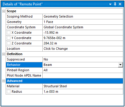
Material: This property is available when the Behavior property is set to . Select a material to define material properties for the beam connection of the Remote Point. Density is excluded from the material definition.
Radius: This property is available when the Behavior property is set to . Specify a radius to define the cross section dimension of the circular beam used for the beam connection of the Remote Point.
| Common Properties | Behavior Options |
 |  |
| Deformable Behavior and Manual DOF Selection Specified | Beam Behavior Specified - Advanced Category Displays |
 |  |