


This section describes the use of joint stops and locks. Topics include:
Overview
Stops and Locks are optional constraints that may be applied to restrict the motion of the free relative degree(s) of freedom (DOF) of most types of joints. Any analysis that includes a valid joint type can involve Stops and/or Locks. For the applicable joint types, you can define a minimum and maximum (min, max) range inside of which the degrees of freedom must remain.
Definition:
Stop: A Stop is a computationally efficient abstraction of a real contact, which simplifies geometry calculations. For Stops, a shock occurs when a joint reaches the limit of the relative motion.
Lock: A Lock is the same as a Stop except that when the Lock reaches the specified limit for a degree of freedom the Lock becomes fixed in place.
Recommendation: Ansys recommends that you:
Use either the Ansys Rigid Dynamics solver (Rigid Dynamics analysis) or the Motion solver (Multibody Dynamic analysis) when performing purely rigid body problems in order to avoid pivoting issues.
Do not use stops for contact modelling.
Stop and Lock Properties
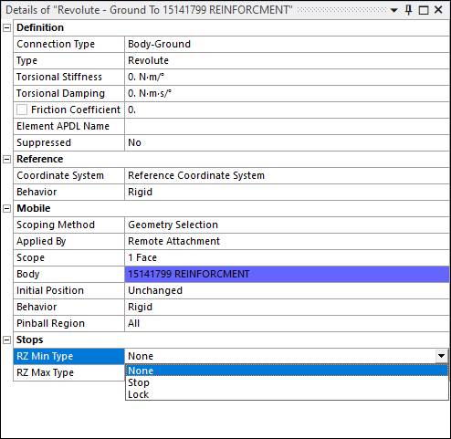
For joints with free relative DOFs, the Details pane displays a group of options labeled Stops. This grouping displays the applicable free DOFs (UX, UY, UZ, ROTX. etc.) for the joint type from which you specify the constraint as a or a (as shown below). By default, no Stop or Lock is specified, as indicated by the default option, . You can select any combination of options. For stops and locks, the minimum and maximum values you enter are relative to the joint’s coordinate system.
Joint Types Support for Stops and Locks
Stops and Locks are applied to the following joint types.
| Joint Type | Stop/Lock Ansys Rigid Dynamics | Stop/Lock Mechanical APDL | Stop/Lock Ansys Explicit Dynamics |
|---|---|---|---|
| Revolute | Yes | Yes | Yes |
| Cylindrical | Yes | Yes | Yes |
| Translational | Yes | Yes | Yes |
| Slot | Translational | Translational | Translational |
| Universal | Yes | Yes | No |
| Spherical | No (Radial Gap is available through Spherical Gap joint) | Yes | No |
| Planar | Yes | Yes | Yes |
| General | Translational, Radial Gap | Translational | Translational |
| Bushing | Translational, Radial Gap | Translational | Not supported |
| Spherical Gap | Radial Gap stop is always defined | Not supported | Not supported |
| In-Plane Radial Gap | Radial Gap stop is always defined | Not supported | Not supported |
| Radial Gap | Radial Gap stop is always defined, translation along Z if free | Not supported | Not supported |
Note:
When using the Mechanical APDL solver, Stops and Locks are active only when Large Deflection is set to On (under Analysis Settings). This is because Stops and Locks make sense only in the context of finite deformation/rotation. If Large Deflection is Off, all calculations are carried out in the original configuration and the configuration is never updated, preventing the activation of the Stops and Locks.
It is important to apply sensible Stop and Lock values to ensure that the initial geometry configuration does not violate the applied stop/lock limits. Also, applying conflicting boundary conditions (for example, applying Acceleration on a joint that has a Stop, or applying Velocity on a joint that has a Stop) on the same DOF leads to non-physical results and therefore is not supported.
Solver Implications
Stops and Locks are available for the Ansys Explicit Dynamics, Ansys Rigid Dynamics, and Mechanical APDL solvers, but are handled differently in certain circumstances by the three independent solvers.
For the solver the shock is considered as an event with no duration, during which the forces and accelerations are not known or available for postprocessing, but generate a relative velocity "jump".
For the Mechanical APDL solver the stop and lock constraints are implemented via the Lagrange Multiplier method. The constraint forces due to stop and lock conditions are available when stop is established
For the Ansys Explicit Dynamics solver the stop/lock event is checked during the timestep. If it is active the timestep is split up such that the free motion is still considered for the first part. The second part of the timestep is computed using either the reversed velocity (while taking into account the restitution factor) or the new fixed DOF. If other stop/locks events are active also, they will be addressed during the next cycle in the solver. Due to the small timesteps in an explicit analysis, this approximation is typically negligible.
Radial Gap Stop
To model clearance in revolute or cylindrical joints, a special type of stop called a radial gap stop can be used. A radial gap stop limits the relative rotation of either the X or Y rotation, limiting the Z axis tilt of the joint's mobile coordinate system with respect to the Z axis of the reference coordinate system. This stop idealizes a revolute joint with a gap between the inner and the outer cylinder that allows the shaft to translate and tilt in the outer cylinder, as shown on the following figure:
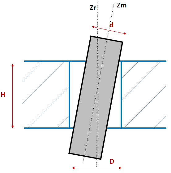
Where:
| d is the inner diameter. |
| D is the outer diameter. |
| H is the height of the joint. |
Important Notes:
The Outer Diameter is considered to be on the reference side of the joint, so you might have to flip reference and mobile on the joint to properly define a radial gap.
The shaft is considered to be infinitely long.
If the joint allows relative translations, the center of the shaft will shift with these translations. The radial gap accounts for this center shift.
The principal axis of the radial gap is Z, meaning that the tilt occurs along the X and Y rotations of the gap.
Radial gap stops do not support tilt angles greater than 1 rad.
Radial gap is always included on imperfect joint types (spherical gap, in-plane radial gap, and radial gap)
Coefficient of Restitution
For the and solvers, Stops require you to set a coefficient of restitution value. This value represents the energy lost during the shock and is defined as the ratio between the joint’s relative velocity prior to the shock and the velocity following the shock. This value can be between 0 and 1. For a restitution value of zero, a Stop is released when the force in the joint is a traction force, while a Lock does not release. A restitution factor equal to 1 indicates that no energy is lost during the shock, that is, the rebounding velocity equals the impact velocity (a perfectly elastic collision).
The coefficient of restitution is not applicable to the stops on the joints when using the Mechanical APDL solver.