


Go to a section topic:
External Model Properties in Workbench
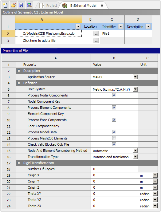
The External Model tab is illustrated below. From this tab, you to modify various properties prior to importing your finite element data into Mechanical. Refer to the Creating and Configuring an External Model System topic in the External Model section for a description of the properties available on the External Model tab.
Model Cell Properties in Workbench
The properties of the Model cell on the Workbench Project page are illustrated below. You use the Mesh Conversion Options group of properties to specify import processes used on the finite element data. Properly defining these properties is important for you to accurately generate the desired geometries in Mechanical.
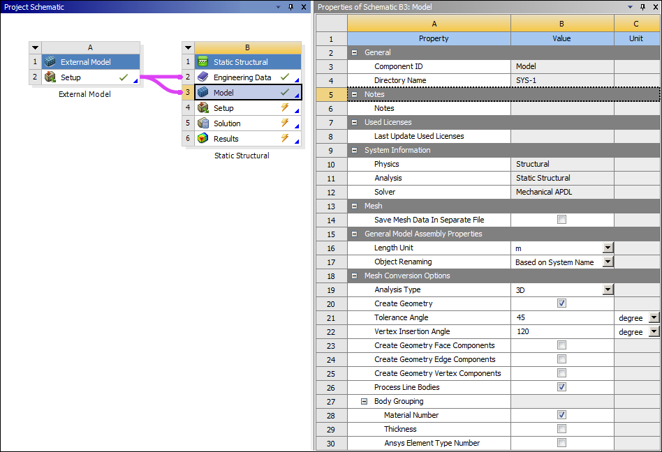
Mesh Conversion Options include:
Analysis Type: Defines the mesh file as (default) or . When working with 2D analysis types, make sure that all of your model’s surface normals point in the same direction using the Rigid Transformation properties available through the External Model feature.
When you set this property to the option, in Mechanical, the application validates that the geometry is two-dimensional (2D) by checking the value of the Length Z property, using CAD units, in the Bounding Box category of the Geometry object. The tolerance used for this check is based on the setting of the 2D Tolerance property (Properties category of the Geometry object). If you change the value of the 2D Tolerance property, you must refresh the analysis on the Workbench project page in order for the application to re-validate the geometry.
Create Geometry: This option is active by default. When selected, the application automatically creates your geometry in Mechanical based on solids, shells, and beam elements (that have an assigned cross-sectional definition) present in the mesh. When imported, a Geometry object is placed in the Outline. Deselecting this option instructs the application to import the mesh only (elements and nodes). When imported, an Element Groups object is placed in the Outline. Element Groups object and its children behave as a Geometry object and its children. That is, the Solid, Surface, and Line elements behave as bodies.
Not creating a geometry dramatically decreases your import time as well as significantly reducing the amount of memory used during the process.
Tolerance Angle: This value determines if adjacent elements are of the same face during the geometry creation process. The geometry creation process identifies groups of element facets on the exterior of the mesh. These generated facets create geometric faces in Mechanical. Then skin detection algorithm scans the exterior element facets and groups them based on a tolerance angle. For example, two adjacent element facets are grouped into the same face if the angle between their normals is less than or equal to the given tolerance angle. Therefore, an angle tolerance of 180o creates only a single face for the whole body while a tolerance of 1o creates an amount of geometric faces which approaches the number of element faces if any curvature is present.
Calculations to synthesize geometries using tolerance angles use the implicit method. Processing nodal components on the same topology will override this method. See the illustrations below for examples of this behavior.
The default Tolerance Angle is degrees. This is the recommended setting.
Vertex Insertion Angle: The Vertex Insertion Angle is the minimum angle to insert a vertex between two free edges of mesh. The default value is degrees. During the generation of the geometry, if two segments of an edge abruptly make an angle greater than the Vertex Insertion Angle, then the edge is split and a vertex is inserted.
Create Geometry Face/Edge/Vertex Components: These options become active when your mesh file contains node-based named selections. When active, the application automatically creates geometric named selections (face/edge/vertex). For a vertex or an edge, the node-based named selection can include only include one node or one edge. For faces, nodes from multiple faces can be included in the node-based named selection. This option will not affect the geometry creation algorithm itself, which is based purely on the mesh adjacency angles as detailed above.
Note: The application automatically transfers geometry-based Named Selections for faces.
Component Key: If you select one or more of the Create Geometry Face/Edge/Vertex Components option, this property enables you to generate geometric components specific to the key name that you enter. The application evaluates keys from the beginning of the string value. For example, a given mesh file has the following components: Fixed_Support1, Fixed_Support2, and Force1. If you enter "Fixed_Support", Mechanical automatically produces Named Selections for Fixed_Support1 and Fixed_Support2, but not Force1.
Process Line Bodies: This property enables you to import finite element line bodies (see Line Bodies) that have a properly defined cross-section. For these finite element line bodies, the following element types are supported.
For CDB files: see the Beam Shape Category in the External Model Supported Element Types section of the Help.
For NASTRAN files: the CBAR and CBEAM element types are supported and require a cross-section property defined via PBAR, PBARL, PBEAM, or PBEAML.
For ABAQUS files: multiple options are available. Primary properties include: *BEAM SECTION, *FRAME SECTION, and *BEAM GENERAL SECTION.
Body Grouping: This property tells Mechanical how to group the elements (of the same type) from the data file. Elements are always grouped by shape and different shaped elements are placed in separate groups. This option controls the number of element groups/bodies created in Mechanical. You use the following options to specify how you want to group elements. You can select one or more (or all) options. Property options include:
(default): Group elements based on the material number assigned to the elements. The application creates a group for each Material Number.
: Group all elements that have the same thickness number.
Ansys Element Type Number: For Mechanical APDL common database (.cdb) files only, this option enables you to group elements by their local Ansys element type that was assigned from the element library. Note that the element type number is the first argument to the ET command in the (.cdb) file.
Important:For LS-DYNA files, Mechanical creates only one part. Elements are grouped into bodies first by element shape then by Part ID as defined in the LS-DYNA file and then (if chosen), by Material Number or Thickness. Therefore each element in a body will have same shape, LS-DYNA Part ID and (if chosen), and same Material Number and Thickness. In addition, each body listed in the Outline has its part name specified using the *PART keyword in the input file.
For ICEM CFD Files, the application uses data internal to ICEM CFD files to group elements into bodies and to create geometric faces. Therefore, the Tolerance Angle is ignored.
Mechanical Interface Options
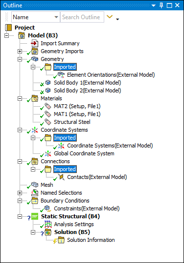
When you import an External Model source file that includes any of the supported finite element data types, Mechanical inserts an “Imported” folder (excluding Named Selections) beneath the corresponding Outline object. As illustrated in the example Outline below, this Imported folder object is a simple group folder that contains child objects for the associated data type.
Selecting a child object of the Imported folder displays the mesh/geometry in the Geometry window, with the imported data type highlighted on the mesh/geometry, as well as the Worksheet. An example of a selected imported spring is illustrated below. The Worksheet displays a summary of all imported data including column headings for the specific data associated with each data entry (connection Type, node ID, etc.). Each row of the Worksheet represents a different set of data. You can sort the table data by clicking on a column heading. The Active field check-box for each Worksheet row enables you to deactivate (suppress) the row. You can also sort active/deactivated table content using the Active column heading. And, based on the number of data items imported, the Worksheet displays 500 (default) data items per worksheet page. Use the display and/or navigational options at the bottom of the window to display more data items per page as well as to step through the available pages of data.
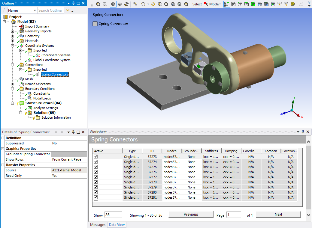
A graphical representation of the data is also shown in the Geometry window. You can choose which data is displayed in the Geometry window using the Show Rows property under Graphics Properties category in the Details view. The Show Rows property includes the following options:
From Current Page (default): Only display the data from the current page in the Worksheet.
From All Pages: Display all of the data for the object independent of the rows visible in Worksheet.
None: Do not display any data in the Geometry window.
In addition, for the following objects, you have the ability to select the color used for the displayed data in the Geometry window through a color selection property in the Details view:
Worksheet
Furthermore, when you select a Worksheet row, the graphical representation of the data in the Geometry window becomes highlighted, such as the green spring shown in the above image. You can also select the graphical representation directly in the Geometry window by activating the Imported Data Highlight option on the Graphics Toolbar. Normal mouse and key combinations for selecting, deselecting, modifying, or clearing selections act just as they do with geometry selections, etc.
In addition, for the above data types, when you select the graphical representation (Point Mass, Spring, etc.) in the Geometry window and right-click, the context menu provides the following applicable options:
> : This option navigates to attached bodies in the tree.
: This option only displays the selected objects in the worksheet. You can revert to viewing a specified number of rows in the Worksheet by editing the column headings via the right-click Show option in the Worksheet.
When the finite element data is displayed in the Worksheet, there are common options you can employ when you right-click on a Worksheet row, including:
Promote: When you promote a Worksheet entry, the data, in whichever form (Coordinate System, Element Orientation, etc.), remains linked to the external system. You can modify the data within Mechanical, however; your changes are not transfer to the external system. In addition, any changes made in the external system will overwrite any modifications you make in Mechanical. Generally, you promote a Worksheet as a scoping in the form of a Named Selection. However, for Imported Bolt Pretensions, you can promote a Bolt Pretension, to a desired environment, in the form of a load.
Copy as new: When you copy a Worksheet entry, a new independent object, based on the type of data, is inserted into the Tree outline. The application assigns a default name to the object based on the data type (Coordinate System, Element Orientation, etc.).
Show: This option enables you to select which columns you wish to display on the Worksheet.
Active: This option enables you to deactivate (suppress) a worksheet row. You can select multiple rows and select the checkbox of any row to activate or deactivate all highlighted rows.
Go To Promoted: This option becomes available after you have promoted a Worksheet entry. This option takes to you the corresponding Tree outline object. This is typically related to a scoping that you have created through promotion. However, for Imported Bolt Pretensions, it can correspond to a Bolt Pretension promoted in the form of a load.
Edit Items: This option becomes available when your finite element data type has editable Worksheet content. It enables you to make changes to the associated data items, such as a node ID. You can select individual or multiple rows as well as the data type tree object. When you select multiple rows or the tree object, the application applies all changes to all of the selected rows or to all of the Worksheet content, respectively.
: Automatically select all rows in the currently displayed page of the worksheet.
Note: Currently, Mechanical only supports the Promote and Copy as new options for the following imported data:
Bolt Pretensions
Contacts
Coordinate Systems
Element Orientations
Flexible Remote Connectors
Point Masses (when scoped to a node of the geometry only)
Rigid Remote Connectors
Requirements and Limitations
Note the following requirements and limitations for importing mesh-based geometries:
The application does not copy input files specified in External Model into the project folders of downstream systems. The application references these files by absolute path only. Be sure you don’t move or rename these files.
Geometry construction is for 3D lines, solids, and shells and 2D planar bodies only. Mechanical ignores any other element types contained in the mesh file.
Mechanical only processes node-based components when attempting to create geometry-based Named Selections for the faces. The application ignores element components.
You cannot change the meshes. That is, you cannot change, clear, or re-mesh once the file has been imported into Mechanical.
Mesh controls (Refinement, etc.) are not supported.
Adaptive Mesh Refinement is not supported.
Geometry is not associative. As a result, if you update the environment, for example, by adding another mesh file, any scoping that you have performed on an object will be lost. To avoid losses to your analysis environment, make sure that you have properly defined the imported Named Selections or criterion-based Named Selections.
The application specifies the Stiffness Behavior property as either or . This is a read-only property.
The Scale Factor Value property on the Geometry object is not supported.