When setting the Method control to a scoped body, you can control whether meshes are to be created on the scoped body with midside nodes or without midside nodes by using the Element Order setting under Definition in the Details View. When setting the Element Order option for a scoped body, choices include Use Global Setting, Linear, and Quadratic.
If you select Use Global Setting, Element Order will be handled as dictated by the global Element Order option. The remaining choices—Linear and Quadratic—have the same descriptions as their counterparts under the global Element Order option. Setting Element Order to Linear or Quadratic for a scoped body will override the setting of the global Element Order option.
If the Element Order is set to Quadratic, and if Straight Sided Elements is set to No, the midside nodes will be placed on the geometry so that the mesh elements properly capture the shape of the geometry. However, if the location of a midside node might affect the mesh quality, the midside node may be relaxed to improve the element shape. Therefore, some midside nodes might not follow the shape of the geometry precisely.
For more information about how the Straight Sided Elements control affects midside nodes, see Straight Sided Elements.
Mixed Order Meshing
Mixed order meshing is supported across bodies for the following mesh methods:
For solid meshing:
For surface meshing:
Note: Mixed order meshing is not supported for Pull.
This means that when scoping one of these mesh methods to bodies in a multibody part, you can set the Element Order option to Quadratic (resulting in higher order elements) for some bodies and to Linear (resulting in lower order elements) for others.
Mixed order meshing is supported whether you are performing Selective Meshing or meshing all of the bodies in the part at the same time. The behavior, and your resulting mesh, is dependent on the meshing order:
For simultaneous meshing, the Quadratic bodies generally have precedence at the interface. In such cases, all of the elements in a lower order body that are adjacent to a higher order body will be higher order elements, thereby creating one layer of quadratic elements at the interface face. These elements will be higher order at the interface face but with dropped midside nodes where adjacent to the linear elements in the mesh.
An exception occurs when a solid body and a sheet body share an interface. In this case, the solid body takes precedence and will be meshed first using its defined element order. Then the sheet body is meshed with midside nodes handled as described for Selective Meshing, below.
For Selective Meshing, the order in which you mesh the bodies determines the precedence. If you first mesh a linear body followed by meshing an adjacent quadratic body, then the linear body has precedence. Elements in the quadratic body that are adjacent to the linear body will be lower order elements. Midside nodes will be dropped from the quadratic elements at the interface face.
If you first mesh a quadratic body followed by meshing an adjacent linear body, then the quadratic body has precedence. Elements in the linear body that are adjacent to the quadratic body will be higher order elements. Midside nodes will be added to the linear elements at the interface face.
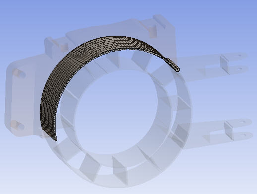
The figures below illustrate an example of mixed order meshing. To obtain the mesh shown in Figure 75: Mixed Order Meshing of a Multibody Part, the global Element Order option was set to Quadratic, resulting in a mesh of quadratic tet elements for the topmost body. The sweep method was applied to the remaining bodies, with the Element Order option set to Linear on the Sweep Method control. This resulted in a mesh of primarily linear hex/wedge elements for the swept bodies, with the hex/wedge elements that are attached to the common interface being mixed order (see Figure 76: Mixed Order Elements).
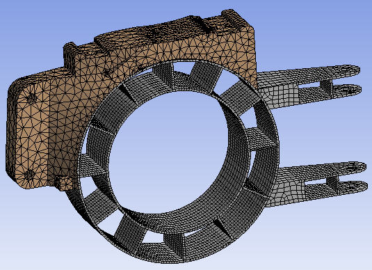
Figure 76: Mixed Order Elements shows the mixed order hex/wedge elements that are attached to quadratic pyramid elements at the interface. On the Mesh Metrics bar graph, mixed order elements are displayed as quadratic element types.