


Cartesian method creates unstructured hexa mesh of mostly uniform size, aligned to the specified coordinate system, and fits it to the geometry. The element size should be smaller than the thickness of the model to prevent the mesher from defeaturing (not capturing) that portion of the model. Alternatively, the defeaturing could be helpful to eliminate dirty geometry smaller than the element size. Cartesian Method is a body fitted meshing.
This method is useful when the geometry features align well with a coordinate system and a regular mesh is desired. Models for explicit dynamics, organic models (models without many feature edges), process industry and electronic components are good examples that could benefit from this mesh method. This method is also recommended for simulating the printing process in Additive Manufacturing.
Note: The Cartesian method must be applied to an entire part. If a body in a multibody part is selected, all bodies in the part are added to the Geometry selection.
To access the Cartesian Method control,
On the Tree Outline, right-click Mesh and click Insert > Method.
Or
On the Tree Outline, click Mesh and click Method in the Mesh Context tab on the Ribbon. Select Method as Cartesian in the Automatic Method Details view.
The Details view has the following options:
Scope
Scoping Method: Allows you to scope geometry bodies or named selection. The default value is Geometry Selection.
Geometry Selection: Allow you to scope the geometry bodies. When you select Geometry Selection, the Geometry allows you to select the geometry from the Geometry window.
Named Selection: Allow you to scope bodies grouped under a named selection.
Definition
Suppressed: Allows you to suppress the selected control. The default value is No. When Suppressed is set to Yes, Active displays the status of the selected control. Active is read-only.
Method: Allows you to select method.
When you select the Cartesian Method option, the Details view expands to include additional settings, many of which are unique to this option. For basic usage that involves obtaining a Cartesian mesh, the procedure is to apply a Method Control to one or more bodies, set Method to Cartesian, and accept the default values of the various settings.
For advanced or specialized usage, adjust the settings as needed. The following is a description of each of these settings.
Element Order: Allows you to select the element order. The default value is Use Global Setting. For information about the Element Order option, refer Method Controls and Element Order Settings.
Type - Allows you to specify how the edge size is determined. Edge size is considered a soft size, allowing for small variations depending on geometry and other settings. The available options are Element Size and Number of Divisions. The default value is Element Size.
Element Size: Allows you to set the element size. You can use the Default setting, which is based on global element size, or manually set the element size. Select the checkbox to the left of the label to parameterize the Element Size.
Number of Divisions: Allows you to set manually number of divisions in Z-direction using Number of Divisions in Z-Diror you can use the Default setting, which is obtained from the model's bounding box size in the z-direction divided by the global element size. The nominal size found from the computation of the number of divisions is also used for the spacing in the x and y dimensions.
Number of Division in Z-Dir: Allows you to set the number of divisions in the Z direction. You can parametrize Number of Divisions in Z- Dir.
Spacing Option: Allows you to force split lines to better capture model features. The available options are Uniform, Key-Points (Auto) and Key-Points (Manual). The default value is Uniform.
Uniform: Uses the specified element size for X, Y and Z spacing. This may result in distorted or missing elements.
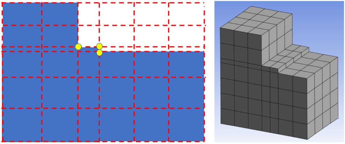
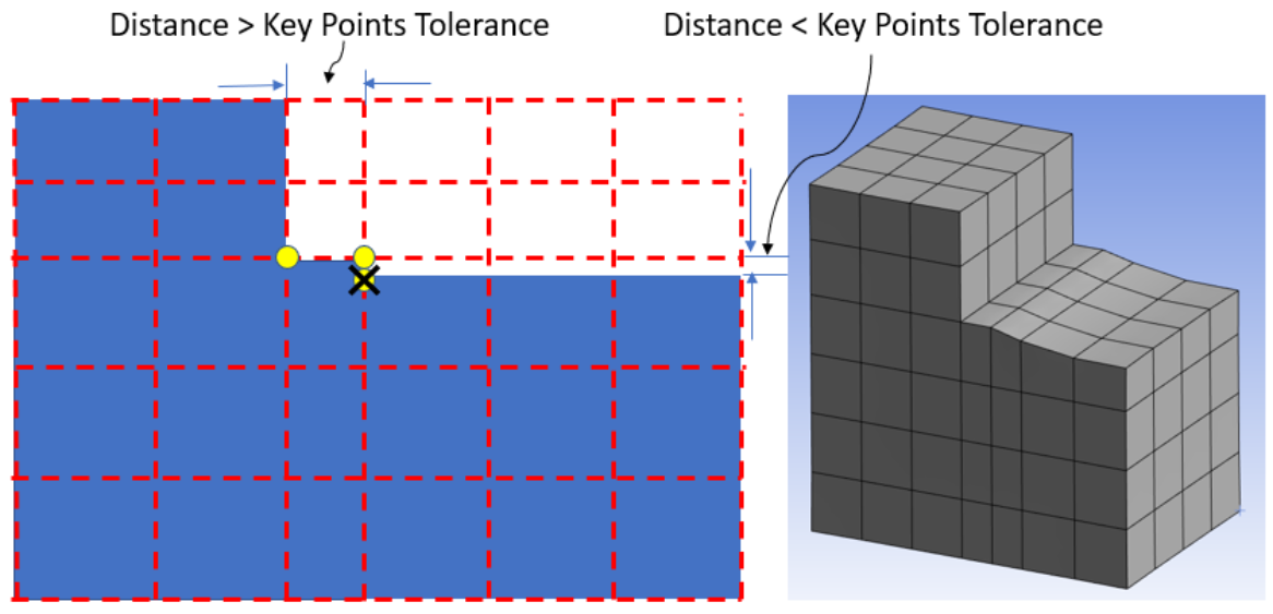
Key-Points (Auto): Check all vertices in the model and add split lines to follow the features, within the specified Tolerance. Then, Key-Points (Auto) adjust the mesh spacing between neighboring split lines so that the hex mesh follows the features.
Key-Points Tolerance: Allows you to set the tolerance to defeature small features and avoid over-refined meshes when corner features are not aligned.
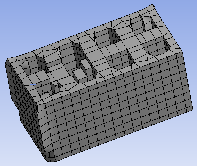
Example without Key-Points
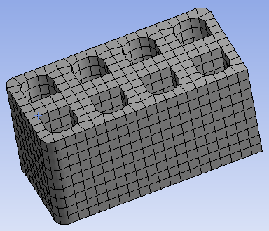
Example with Key-Points Tolerance equals zero
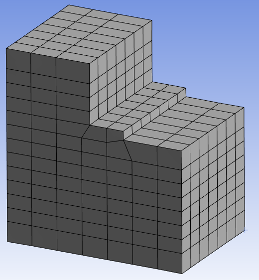
Example with Key-Points Tolerance ≥ geometry step size
Key-Points (Manual) - Allows you to select vertices manually to create split lines in each of the X, Y and Z directions. Mesh spacing is adjusted between neighboring splits. Additional split lines may be added by the mesher as required to follow the features. The available options for the Key-Points (Manual) in X, Y and Z direction are:
Vertices in X: Allows you to set vertices manually to create split lines in X-direction.
Vertices in Y: Allows you to set vertices manually to create split lines in Y-direction.
Vertices in Z: Allows you to set vertices manually to create split lines in Z-direction.
Note: Key-Points are the corner points of the features. Specifying key-points matches cartesian splits with the corner points so that the feature is respected.
Advanced
Projection Factor: Allows you to set the balance between mesh quality and capturing the geometry.
Set a value between 0 and 1. If the Projection Factor is set to 0, the Cartesian mesh will have high quality hexa elements that approximate the geometry surface through stairstepping. Increasing the value of Projection Factor will force the mesh to more closely follow the geometry surface, but with reduced element quality. If the Projection Factor is set to 1, most of the boundary nodes will project to the geometry and perturb only those causing bad element quality. However, some hexa elements may have pairs of coplanar faces to fit a planar geometry surface.
The following demo is presented as an animated GIF. View online if you are reading the PDF version of the help. Interface names and other components shown in the demo may differ from those in the released product.The image shows the effect of decreasing the Projection Factor for a simple geometry with two sides aligned with the global coordinate system.
The default value of Projection Factor is 0 for Additive Manufacturing Process simulations. Specifically, if the AM Process object is present in the Project tree when a Cartesian method is added, the Projection Factor is automatically set to 0. When you want to generate supports from the meshed body, the Projection Factor must be set to 0.
Project in constant Z-Plane: Allows you to use for print simulation in Additive Manufacturing.
If enabled, the x and y coordinates of the Cartesian mesh are modified while maintaining a constant height in the Z-direction. The final mesh is much tighter to the geometry. This option is enabled by default if the AM Process object is present in the Project tree.
Stretch Factor in X: Allows you to modify the Aspect Ratio of the hex mesh in the X-dimension.
Stretch Factor in Y: Allows you to modify the Aspect Ratio of the hex mesh in the Y-dimension.
Stretch Factor in Z: Allows you to modify the Aspect Ratio of the hex mesh in the Z-dimension.
Strech Factor is useful to reduce the element count for a geometry that may be elongated or shortened in one dimension. In this image, Stretch Factor in Z has been set to 3.0 while X and Y remain at 1.0. Mesh elements sizes can be up to about 3x larger in the z-dimension than x-dimension and y-dimension, within the constraint of the Projection Factor.
Note: The process for applying the Stretch Factor depends on how edge sizing is determined. However the result on aspect ratio is the same.
When Type = Element Size, the stretch factor applies a multiplier to the element size, aligned to a selected dimension. For example, when Element Size = 0.1 and stretch factors of 0.5, 1, and 2 are applied, then the dimensional mesh element size will be approximately 0.05, 0.1 and 0.2.
When Type = Number of Divisions, the stretch factor scales the other dimensions while preserving the specified number of divisions in the z-dimension. For example, when stretch factors are 0.5, 1, and 2, then the nominal element sizes are scaled by approximately 1/4, 1/2 and 1 to preserve the number of divisions in the z-dimension.
Note: Body Fitted Cartesian Method supports soft edge sizing.
Coordinate System: Allows you to choose the coordinate system to which the mesh is aligned. The default value is Global Coordinate System.
Write ICEM CFD Files: Allows you to set options for writing Ansys ICEM CFD files. Refer to Writing Ansys ICEM CFD Files for details.
Smooth Mesh Spacing: Allows you to perform edge length based smoothing when Smooth Mesh Spacing is set to Yes. The default value is Yes when the Physics Preference is Explicit. For other Physics Preference, the default value is No.