


Creates a three-dimensional mesh in the circumferential direction on a surface body model that is based on specified nodal planes and an axis. This feature supports edge and vertex scoping only. From these surface model edges and vertices, you can generate three-dimensional node-based Named Selections that you can then use as scoping items for other simulation options such as loading conditions and/or results.
This feature uses the Mechanical APDL elements SOLID272 and SOLID273.
 |
Object Properties
The Details Pane properties for this object include the following.
| Category | Properties/Options/Descriptions |
|---|---|
|
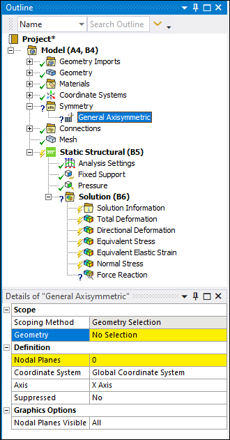
Scope |
Scoping Method: Read-only field. Geometry Selection is the only supported option. Geometry: Specify the geometry using geometry selections. You can specify any planar surface body. Only Body scoping is supported. |
|
Definition |
Nodal Planes: Specify the desired number of nodal planes.
Your entry defines the number of planes around the axis and on which nodes should be
generated. The entry for this property can be either Coordinate System: As needed, specify a coordinate system. The default setting is the . Axis: Specify the axis about which the axisymmetric mesh is generated. Options include , , and . This setting must lie along the body, it cannot intersect the body, and it must be specified on the same plane as the selected surface body. |
|
Graphics |
Nodal Planes Visible: Select the range of planes for which the mesh or results can be displayed. The maximum number of planes that can be displayed is defined by the Nodal Planes property. Options include (default) and . Changing the setting to specifies a desired range, such as 1-6 or 6-12, of the number of planes that you want to display for the mesh and results objects. When you select , the following properties display:
|
Tree Dependencies
Insertion Methods
Select the Symmetry object and select the option on the Symmetry Context Tab.
Right-click the Symmetry object and select > .
Right-click Options
In addition to common right-click options, relevant right-click options for this object include:
>
API Reference
See the General Axisymmetric section of the ACT API Reference Guide for specific scripting information.
Additional Related Information
See the following sections for more information: