


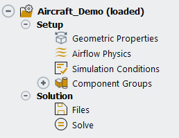
Once a simulation is loaded, a simulation tree appears in the Outline View. The name of the simulation you have loaded appears at the top of the tree along with the text (loaded). Underneath the name of the simulation, the Outline View tree is displayed.
The Outline View tree contains steps that guide you through the setup of Fluent Aero simulation. These steps should be worked through sequentially to completely set up the problem. In the typical workflow, this tree is composed of six steps. Four steps under Setup (Geometric Properties, Airflow Physics, Simulation Conditions, Component Groups), and two steps under Solution (Files, Solve).
The first step in the Fluent Aero workflow is to define geometric properties, including orientation and reference sizes.
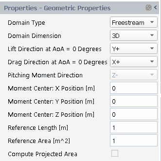
Domain Type
This setting is used to describe the type of computational domain that surrounds your object of interest. There are two available settings: or . If you follow the guidelines for name and boundary type outlined in Freestream or WindTunnel Domain Type Requirements, this setting may be set automatically upon importing a case file. This setting cannot be changed after a calculation has been performed.
Domain Dimension
This setting should be used to define whether the domain consists of a full 3D geometry (), or a 2D geometry that has been extruded to construct a 1 cell thick 3D mesh ()
Lift Direction at AoA = 0 Degrees
This setting defines the cartesian direction that corresponds to the direction of the Lift vector when the geometry is operating at a 0-degree angle of attack. This setting provides Fluent Aero with an orientation, allowing for the correct application of the Angle of Attack and Angle of Sideslip input variables, and ensuring the accuracy of aero forces calculations in both the supported body-fixed and wind-fixed coordinate systems. The geometry must be oriented as aligned with a cartesian axis such that a cartesian direction can be selected.
Drag Direction at AoA = 0 Degrees
This setting defines the cartesian direction that corresponds to the direction of the Drag vector when the geometry is operating at a 0-degree angle of attack. This setting provides Fluent Aero with an orientation, allowing for the correct application of the Angle of Attack and Angle of Sideslip input variables, and ensuring the accuracy of aero forces calculations in both the supported body-fixed and wind-fixed coordinate systems. The geometry must be oriented as aligned with a cartesian axis such that a cartesian direction can be selected.
Pitching Moment Direction
This setting defines which cartesian direction corresponds to the direction of the Pitching Moment. It is setup automatically depending on the Lift and Drag direction settings.
Moment Center: X-, Y-, Z- Positions [m]
These settings define the position in meters of the Pitching Moment using the cartesian coordinates of the mesh.
Reference Length [m]
This setting defines the reference length in units of meters, which is used for the computation of aerodynamic coefficients.
Reference Area [m^2]
This setting defines the reference length in units of square meters, which is used for the computation of aerodynamic coefficients.
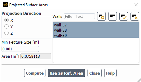
Compute Projected Area
Enabling this option opens the Projected Surface Areas tool window that allows you to compute the reference area of your geometry. Set the Projection Direction and select the Walls that you would like to use for the reference area computation. Click . If you are satisfied with the value that appears in the Area [m^2] box, click to fill the Reference Area [m^2] box with this value.
The Geometric Properties step also contains the following optional command:
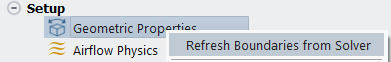
As described in the Case File Requirements, it is recommended that the boundary types of a .cas[.h5] file have been setup properly in a Fluent Solution workspace or a Fluent Meshing workspace before it is imported into Fluent Aero. However, if the boundary types of a .cas[.h5] file have not yet been setup before loading into Fluent Aero, the command can be used to open the background solver window, where the boundary types can be redefined. These boundary types can then be updated in Fluent Aero by right-clicking Geometric Properties and selecting
Once the geometric properties have been defined, you can continue to the next step.
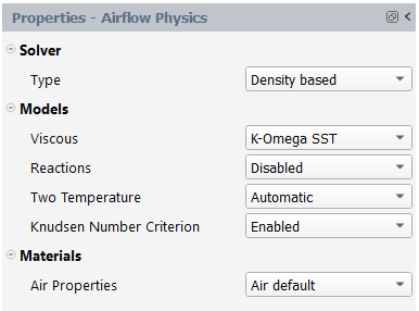
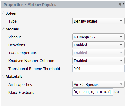
The second step in the Fluent Aero workflow is to define the solver type, the viscous model and the air properties and to enable or disable reactions and the two temperature model during simulations.
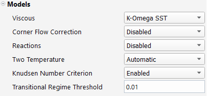
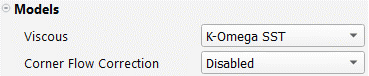
If is enabled under → → Aero, the Corner Flow Correction of a viscous model and the Transitional Regime Threshold of the Knudsen Number Criterion can be specified in Models.
Solver
Type
This setting defines the RANS solver formulation to use during calculations. is set by default while can be selected. Depending on the solver type, some options will be visible inside the Outline View Properties panels. For more information regarding these options, consult Using the Solver in the Fluent User's Guide in the Ansys Fluent User's Guide.
Models
Viscous
This setting defines the viscous model to use during the simulation. Unless otherwise specified, default viscous model constants from the Fluent workspace are applied to each model. For more information regarding these turbulence models, consult Viscous Model Dialog Box in the Fluent User's Guide and Modeling Turbulence in the Fluent User's Guide in the Ansys Fluent User's Guide.
This is the default setting. By selecting this model, the viscous heating and production limiter will be activated in the background solver session.
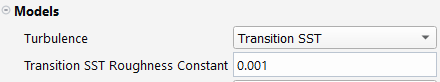
The same turbulence model as above, but with intermittency transition included. By selecting this model, the Transition Model will be set to . Moreover, the viscous heating, production Kato-Launder and production limiter will be activated in the background solver session.
When selected, viscous heating and Transition SST Roughness Constant correlation are applied by default. The Transition SST Roughness Constant will appear as an input option. This value will have a significant effect on the laminar to turbulent transition location. Selecting this model will also cause viscous heating and production limiter to be activated in the background solver session.
This is a more advanced turbulence model that is available as a beta option. This model is a 2 equations hybrid RSM that allows you to capture secondary flow motion driven by turbulence anisotropies or to better represent flows with strong swirl or streamline curvature. By selecting this model, the viscous heating and production limiter will be activated in the background solver session.
This option allows you to use the one-equation Spalart-Allmaras model which was designed specifically for aerospace applications.
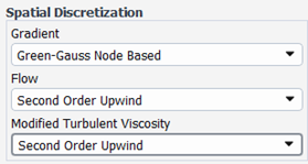
Note: When selected, the spatial discretization of the Modified Turbulent Viscosity will be set to Second Order Upwind instead of the default Fluent Workspace value, which is First Order Upwind.
This option allows you to specify laminar flow with the viscous heating enabled in the background solver session.
This option allows you to specify distinct viscous models for varying flow regimes based on Reynolds number. When selected, two sections, Transition and Fully Turbulent appear below, allowing you to define the Reynolds Number Threshold and Viscous Model to apply for each flow regime. For design points with Reynolds number below the Reynolds Number Threshold of the Transition flow regime, the viscous model is applied.
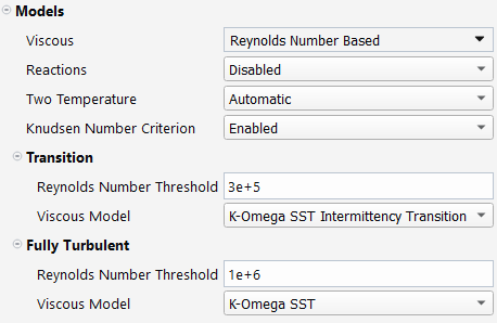
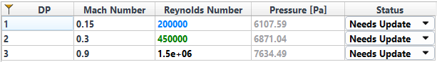
When is selected and simulation conditions are defined, a Reynolds Number column will automatically appear in the input design point table. The Reynolds number is blue for laminar flows and green for transition flows. For fully turbulent flows, the color used follows the standard rule of any other parameter of the Design Point Table.
When selected, Fluent Aero will not apply settings to the turbulence model. Instead, it will use the turbulence model settings in the initial case file, or from the Solution workspace window (Models → Viscous). This option allows you to have full access to the list of advanced turbulence models inside the Fluent Solution workspace. To make advanced changes to the turbulence model, while the case file is already loaded, use the Show Solution Workspace command, and in the window that appears, make the appropriate changes in the Viscous panel.
This option becomes available when Advanced Settings is activated and a viscous model that supports corner flow correction is selected.
Reactions
This setting allows you to enable or disable reactions as needed. When reactions are enabled, the Two Temperature model will be automatically set to and you can choose a mixture model under Materials → Air Properties to account for the species transport and reactions phenomena. The species model settings of the Solution workspace shown below will be applied.
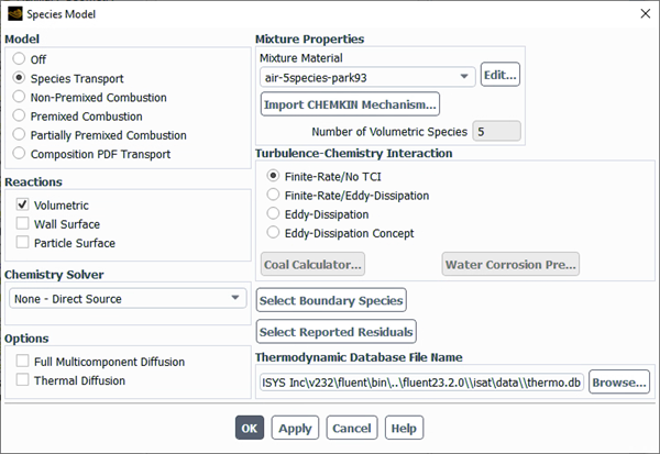
In the above image, the Setup → Models → Species (Species Transport, Reactions) option within Fluent allows the use of a mixture to model the transport of multiple chemical species in a fluid flow. The Reactions → option enables modeling of reactions occurring within the fluid volume. The Chemistry Solver allows you to specify the chemistry model. As for the density-based solver, the recommended option is due to the strong coupling between the chemistry source terms and species mass equations. Fluent Aero uses the default reaction mechanisms of the selected mixture. To use them, the Turbulence-Chemistry Interaction is set to . Refer to Modeling Hypersonic Flows Using the Two-Temperature Model for more information on default reaction mechanisms.
Two Temperature
This setting controls the Two Temperature model in your Fluent Aero simulations, which can improve the accuracy when performing hypersonic flow simulations. This model is only available if Solver Type is set to . For more information regarding this model, consult Modeling Hypersonic Flows Using the Two-Temperature Model in the Fluent User's Guide.
Note: The
cfd_hsflicense increment and thehsflibrary are required to use this model. Contact your Ansys representative to check for the availability of both the license increment and thehsflibrary. If either of these are not available, the Two Temperature will be set to .When selected, Fluent Aero uses the Flow Range for each design point to determine if the Two Temperature model is enabled or disabled. If the Mach number for the design point is greater than or equal to 4.5, Fluent Aero will register that the Flow Range is hypersonic, and will activate the Two Temperature model. If the Mach number for the design point is less than 4.5, Fluent Aero will register that the Flow Range is not hypersonic, and will disable the Two Temperature model.
When the two-temperature model is activated in Fluent Aero, its default spatial discretization scheme and under-relaxation factor for the two-temperature model will be applied. The Flow, Turbulence and Two-Temperature model equations under Solution → Controls → in the Solution workspace will be resolved. Refer to the Materials → Air Properties section under Airflow Physics for the material properties set in Fluent Aero when the two temperature model is activated.
When selected, Fluent Aero will ensure that the model is enabled for all design point calculations. The settings imposed by Fluent Aero are the same as when is set to .
When selected, Fluent Aero will ensure that the model is disabled for all design point calculations.
When selected, Fluent Aero will not apply settings to the model. Instead, it will use the model settings in the initial case file, or from the Solution workspace window (Models → General). If the model is set to , the Air Properties must also be set to .
Knudsen Number Criterion
This setting controls the application of the Knudsen Number Criterion. This criterion defines the flow regime (above this number) at which the continuum hypothesis no longer provides a reasonable representation of the fluid’s behavior and where rarefied gas conditions to prevail. Above this number, the airflow transitions from the continuum hypothesis to the free molecular regime, which is estimated to occur at Knudsen number (Kn) of 0.2. Fluent Aero will automatically apply appropriate viscous models and wall shear conditions to improve the reliability of the RANS model. Fluent Aero automatically calculates the Knudsen number for each design point based on the reference length, material properties, and simulation conditions. The RANS model may not be appropriate at Kn >= 0.2 even with the application of the Knudsen Number Criterion. For more information on the Knudsen number and conditions for rarefied gases, refer to Partial Slip for Rarefied Gases in the Fluent User's Guide.
When selected, laminar flow and partial slip wall conditions will be automatically applied to design points with a Knudsen number above the threshold. For other design points, the viscous model specified in Models → Viscous and no-slip wall boundary conditions will be applied. By default, partial slip wall conditions are set on all walls but can be disabled on specific walls. The latter can be done by locally disabling Knudsen Number Criterion per wall under Component Groups. The default threshold value of the Knudsen number for the transitional (continuum to rarefied) regime is 0.01.
When selected, the viscous model specified in Models → Viscous and no-slip wall condition will be applied on all walls for all design points.
Transitional Regime Threshold
This setting is accessible when is activated. It allows you to adjust the Knudsen number threshold, indicating the start of the transitional regime for rarefied gases. The default value is 0.01, and you can modify the threshold within the range of 0.002 to 0.05.
Materials
Air Properties
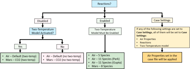
In Fluent Aero, different options are available for Air Properties. This mainly depends on the activation of Reactions. When Reactions are disabled, Air Properties can be set to or, representing Earth and Mars atmosphere, respectively. Two types of Air Properties are supported for and for and are dependent on the activation of the Two Temperature model. When the Two Temperature model is activated, material properties such as specific heat, thermal conductivity and viscosity with higher temperature bounds are used and are more appropriate for hypersonic flows. For more information, refer to Air Default and Mars CO2 sections under Airflow Physics. When Reactions are enabled, species transport and reactions will be accounted for in your simulation. Moreover, you can select , or as Air Properties, which represent Earth and Mars atmospheres, respectively. These options correspond to the , and mixtures available in the Solution workspace. Additionally, if the is enabled, becomes available.
The diagram below provides an illustration of the different Air Properties that are available in Fluent Aero, depending on whether reactions are enabled using species and both the Two Temperature model and Case settings are selected.
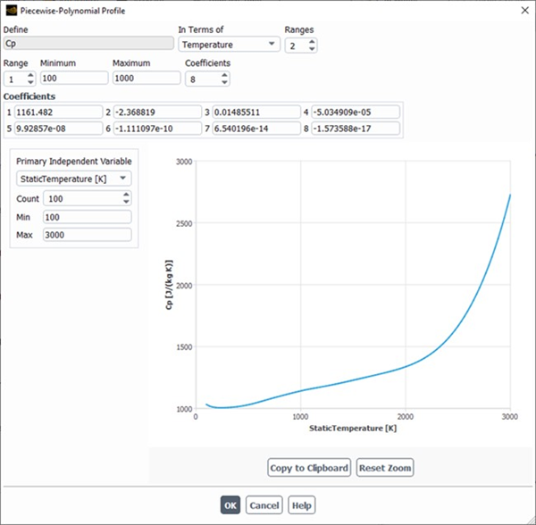
All default air properties inside Fluent Aero follow the ideal gas law assumption. Isentropic relations are used to link total to static pressures and temperatures. Moreover, air properties should respect the following specific heat definition.
When is selected:
When is selected:
When a mixture material or is selected as Air Properties in Fluent Aero,
 is calculated based on the mass fraction of each
species in Fluent Aero or the material settings defined in the case
file.
is calculated based on the mass fraction of each
species in Fluent Aero or the material settings defined in the case
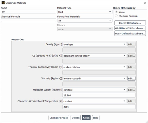
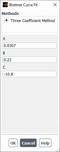
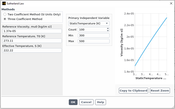
file.When selected, Fluent Aero will set an appropriate material property for air that depends on the activation of the Two Temperature model. Fluent Aero’s typical default air properties, when the Two Temperature model is disabled, are shown below.
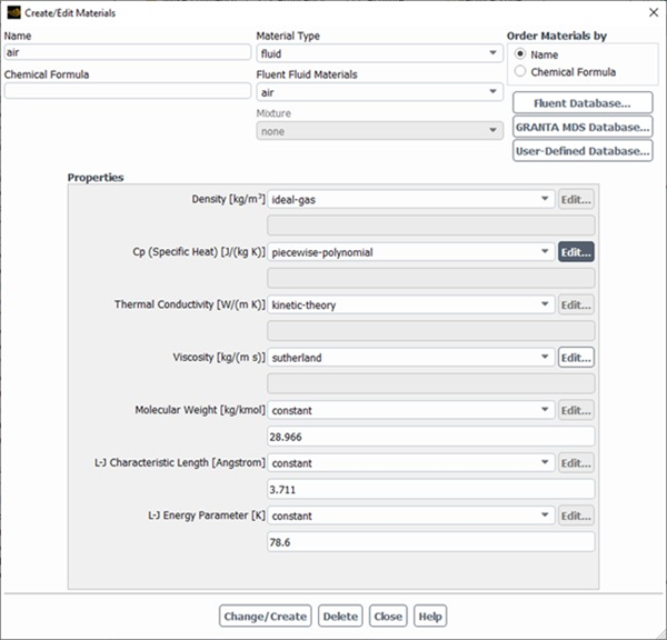
Fluent Aero’s alternate default air properties, when the Two Temperature model is enabled, is shown below.
For more information regarding these air property equations, consult Specific Heat Capacity as a Function of Temperature in the Fluent User's Guide and Modeling Hypersonic Flows Using the Two-Temperature Model in the Fluent User's Guide.
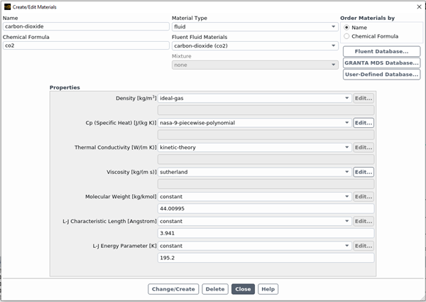
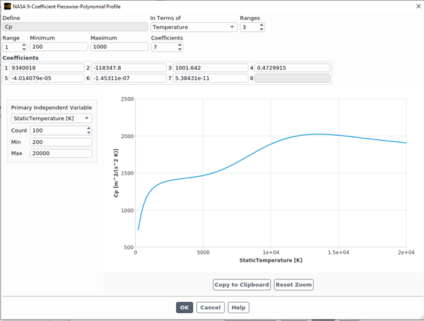
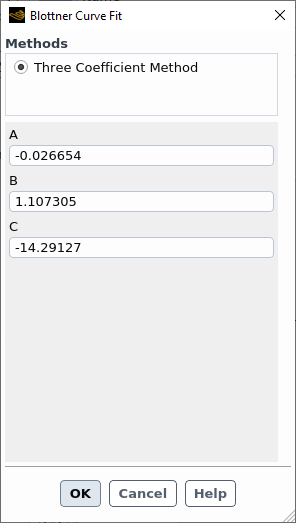
When selected, Fluent Aero will set an appropriate material property for CO2 that depends on the activation of the Two Temperature model. Fluent Aero’s typical default fluid properties, when the Two Temperature model is disabled, are shown below.
Fluent Aero’s alternate default air properties, when the Two Temperature model is enabled, is shown below.
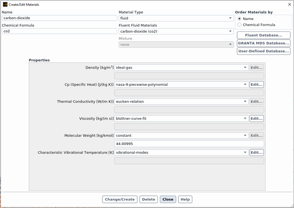
For more information regarding these air property equations, consult Specific Heat Capacity as a Function of Temperature in the Fluent User's Guide and Modeling Hypersonic Flows Using the Two-Temperature Model in the Fluent User's Guide.
, , or
These Air Properties options are available only when both Reactions and Two Temperature are set to . Additionally, the for must be activated. When one of these species option is selected (see Table 3.1: Mixture Mapping Table Between Fluent Aero and Fluent Workspace), Fluent Aero will set its equivalent name in the Fluent workspace as the air mixture representation of the atmosphere and will use it as the fluid cell zone material. Only and account for ionization effects. Mixture and species properties are set by the two-temperature model and can be viewed in the background solver session. Only material properties for air-5species-park93 and mars-8species-park are summarized in the appendix. For more information, consult Modeling Hypersonic Flows Using the Two-Temperature Model in the Fluent User's Guide.
Table 3.1: Mixture Mapping Table Between Fluent Aero and Fluent Workspace
Fluent Aero Fluent Air - 5 Species air-5species-park93 Air - 11 Species (Park) air-11species-park93 Air - 11 Species (Gupta) air-11species-gupta Mars - 8 Species mars-8species-park Note: To use this feature in Fluent Aero, the Two Temperature model must be . This model is only available if you have access to the
cfd_hsflicense increment and thehsflibrary. If either yourcfd_hsflicense increment orhsflibrary is unavailable, a message will be printed to your console log. Contact your Ansys representative to add this increment or library if needed.When selected, Fluent Aero will not apply its default settings to the Air Properties. Instead, it will use the Material Properties for Air as setup in the initial case file, or from the Solution workspace window (Materials → Fluid → air). If the Two Temperature model is set to , then the Air Properties is also set to .
Note: You should be aware that Fluent Aero does not monitor changes made to the settings under . For instance, after Results have been calculated with Air Properties set to , the status of all the design points will be set to . If some material properties are modified inside the Fluent Solution workspace, the status of all design points will remain to instead of .
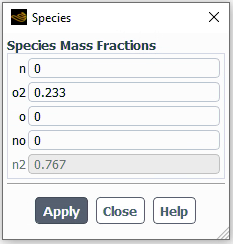
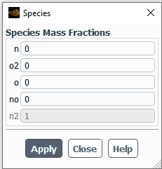
Mass Fractions
When a mixture is selected in Air Properties, this option sets the mass fraction of each species of the mixture.
To modify the Mass Fractions, click . A new panel will open where you can set the mass fraction for each species. The mass fraction of the last species will be computed automatically. The sum of species’ mass fractions must equal one. These will be applied at the inlets of the or groups.
Air Properties Used During the Conversion of Flight Conditions to Boundary Conditions
Fluent Aero supports different Flow Speed input parameters: , Mass Flow Rate, and . Depending on which parameter is used in the definition of the underlying boundary condition in the Solution workspace (Mach, velocity, or mass flow rate), a conversion between them may be required. In addition, Reynolds number, total pressure, and total temperature can also be imposed as input parameters. These parameters must be converted to static pressure and static temperature before applying them as Dirichlet boundary conditions at the inlet of the computational domain. Proper conversion of these conditions must also consider the type of air properties that have been selected as these properties should be consistent between boundary surfaces and the remaining cells that compose the computational domain. For example, when using a mixture in Fluent Aero, the material properties such as density and specific heat ratio of the mixture are calculated by taking into account the mass fractions. If Air Properties is set to , these properties will be computed using the material settings in the case file.
The following describes the process and equations used to perform some typical conversions while accounting for air properties.
Equations to Convert Flow Speed Parameters
Mach number and mass flow rate definitions are used to convert Flow Speed parameters to velocity, Mach and mass flow rate inlet boundary conditions of the Solution workspace.
with
 being the normal area of the inlet
boundary surface.
being the normal area of the inlet
boundary surface.For instance, in a WindTunnel simulation, if was selected as the Flow Speed parameter, a conversion to mass flow rate will occur since a mass-flow-inlet boundary condition is applied at the inlet of a wind tunnel simulation in Fluent Aero. Replacing the speed term in the mass flow rate definition by the Mach number definition, an expression of the mass flow rate with respect to Mach number is obtained therefore allowing its conversion.
Equations to Convert Pressure & Temperature Parameters
The definition of Reynolds number and isentropic relations are used to convert Reynolds number, total pressure, and total temperature quantities to static pressure and static temperature inlet/outlet boundary conditions in the Solution workspace.
For instance, in a far-field simulation, if the Reynolds number is selected as the Pressure and Temperature parameter, this parameter is automatically converted to static pressure by combining the equation state with the Reynolds number definition and imposed at the pressure-far-field of the computational domain. The following steps describe how this conversion is done when default air properties have been selected and the Two Temperature model is disabled.
Firstly, the static pressure can be expressed through the equation of state of the ideal gas.
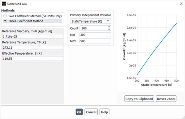
Secondly, the density is computed from the definition of the Reynolds number. The molecular viscosity is obtained using the Sutherland’s law which is the default viscosity model when the two-temperature model is disabled. The velocity
 is either given or converted from
the Mach number or mass flow rate.
is either given or converted from
the Mach number or mass flow rate.Finally, the static pressure can be expressed as
Another example, if is selected in Air Properties and total quantities are selected in the Pressure and Temperature parameters, these parameters are automatically converted to static pressure and temperature. These values are then imposed at the inlet or outlet of the computational domain. The following steps describe how total conditions are converted to static pressure and temperature when default air properties have been selected and the two-temperature model is disabled.
Firstly, an initial approximation for a specific heat ratio of 1.4 is used to obtain an estimate of the static temperature based on isentropic law.
Secondly, substitute the estimated
 into the piecewise-polynomial
model of the specific heat
into the piecewise-polynomial
model of the specific heat  to obtain a more accurate value of
 which is then used to compute a
new specific heat ratio,
which is then used to compute a
new specific heat ratio,Thirdly, substitute the value of the specific heat ratio into the isentropic relation of temperature. Fluent Aero iterates up to 5 times the steps described above. If after 5 cycles, a 0.5 K tolerance is not reached between cycles, a warning message will appear in the console. The final value of the static temperature is then used to compute the specific heat, and finally the static pressure is obtained from the isentropic relation of pressure.


In this step, you define a matrix of flight or wind tunnel conditions (referred to in Fluent Aero as design points). For each design point, Fluent Aero will calculate and post processing an aerodynamic CFD solution.
Note: The conditions applied in this section will be applied to the inlet and outlet boundary zones that are part of the Freestream or Wind Tunnel component groups.
Design Points
Number of Design Points
The single simulation mode is used to investigate the results of a simulation of a single design point using a single flight condition. The Number of Design Points entered here will determine the number of rows in the Input: Design Points table.
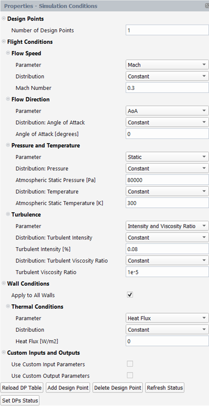
Flight Conditions
This section contains inputs to define the conditions used to perform your aerodynamic simulations. Settings applied in this section will control the inlet and outlet boundary zones that are part of the Freestream or Wind Tunnel component groups.
There are four categories that are used to input these conditions settings: Flow Speed, Flow Direction, Pressure and Temperature and Turbulence. Each category contains Parameter settings where the specific input parameter associated with that category can be selected, a Distribution setting - where the value used for the input can be defined as for all design points or varied with a distribution or distribution for all Design points.
Using the Distribution Setting in Flight Conditions
The Distribution setting works similarly for all three categories of flight conditions, and is described below.
Distribution: Constant
If a Distribution is set to , an input is revealed to enter the constant value of selected parameter to be used for all design points. This is shown in the image below using the Flow Speed → Parameter → as an example.

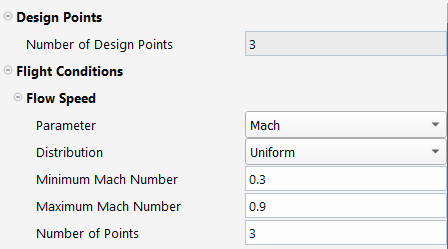
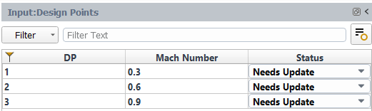
Distribution: Uniform (Single Parameter)
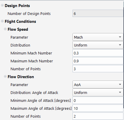
If a Distribution is set to , inputs are revealed to enter the Minimum Mach Number and Maximum Mach Number value as well as the Number of Points to use for the selected parameter. These values will be used to fill the Input: Design Point table that appears above the graphics window in the user interface. Furthermore, the Number of Design Points setting will be greyed out and automatically set to match the Number of Points set for the uniform distribution of the selected parameter.
Distribution: Uniform (Multiple Parameters)
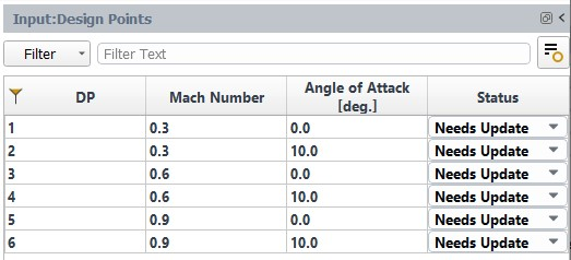
If the Distribution of multiple input parameters are set to , the Input: Design Point table will be generated to contain design points for every combination of inputs from each parameter that is set to use a uniform distribution. Furthermore, the Number of Design Points setting will be updated to match the number generated by using multiple uniform input parameters. In the image below, both and are set to use a Distribution → , and a total of six design points are generated.
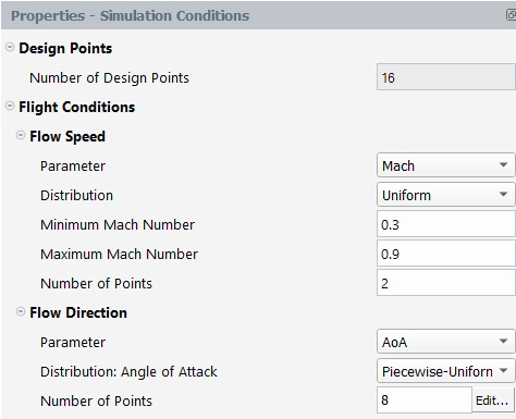
Distribution: Piecewise-Uniform
This option is only available for the Distribution: Angle of Attack setting.
If the Distribution is set to , a Number of Points input is revealed which gives a summary of the number of points used in the currently defined distribution.
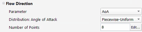
To modify the Distribution, click . The Set Piecewise Uniform Distribution dialog opens.
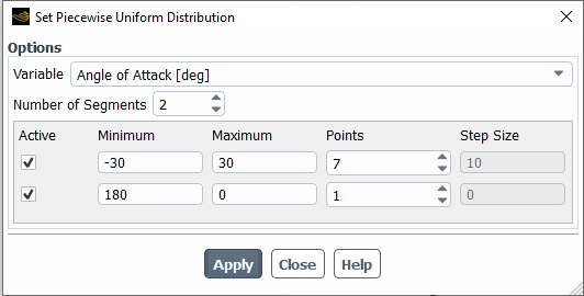
The following options are available:
Variable
Select the input variable for which the piecewise uniform distribution will be applied. For now, only the variable can be used.
Number of Segments
Choose the number of uniformly distributed segments that will be used to define your piecewise-uniform distribution. Each segment defines a set of uniformly distributed points. All segments combined make up the total set of points that define the distribution.
When enabled, this segment will be active, and its points will be created in the Input: Design Points table.
Minimum
Set the minimum value of the uniformly distributed segment.
Maximum
Set the maximum value of the uniformly distributed segment. The maximum value can be set to
0when creating a single point segment.
Points
Choose the number of points to use on the uniformly distributed segment. If a value of 1 is used, a single point segment will be created with a value equal to the Minimum value.
Step Size
This value displays the step size between each point on the uniformly distributed segment.
Clicking will cause the distribution to generate the list of design points in the Input: Design Points table. If the selected segments contain any overlapping values (for example, two segments produce the same value), then only one point will be generated in the table.
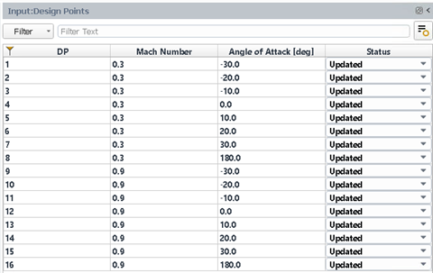
Furthermore, the Input: Design Points table will generate design points for every combination of parameters that is set to or . For example, the following Input: Design Points table was generated with the distribution on and a distribution on .
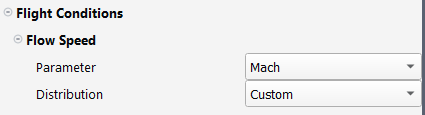
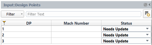
Distribution: Custom
If a Distribution is set to , empty cells are generated in the Input: Design Points table where you can enter a custom value for each design point.
Flow Speed
This section contains inputs to define the flow speed of the ambient flight conditions used to perform your aerodynamic simulations. Settings applied in this section will be applied to the Inlet boundary zones that are part of the or component groups.
Parameter
This setting defines the type of input parameter that will be used to define the flow speed of the condition. number or (m/s) can be selected.
Mach
Mach number is used to define the speed condition for each design point.
True Airspeed
True Airspeed [m/s] is used to define the speed condition for each design point. If is used as the Flow Speed Parameter, only or Parameter can be specified in the Parameter section of Pressure and Temperature.
Mass Flow Rate
Mass Flow Rate [kg/s] is used to define the inlet flow rate for each design point. This input parameter is only available if your Domain Type is set to . If Mass Flow Rate is used only or Parameter can be specified in the Parameter section of Pressure and Temperature.
Note: Depending on the parameter used in Flow Speed (, or ), a conversion may be required if this parameter is not directly supported by the inlet boundary type present in the case file. For example,if a WindTunnel simulation is being set up using as input parameter in Fluent Aero, this number will be converted to a mass flow rate since the boundary type of the case file will be set to mass-flow-inlet. Refer to Airflow Physics for more details about how these conversions are performed and the airflow properties that are used.
Distribution
This setting defines how the value of the input parameter selected above is distributed across each design point. , or can be selected. Refer to Using the Distribution Setting in Flight Conditions under Simulation Conditions for a more complete description of how this setting is used.
Parameter and Distribution Specific Input Values
Depending on what is selected for Parameter and Distribution, further inputs to control the values to use for the Flow Speed input parameter will be revealed under Flow Speed or in the Input Design Point table.
Flow Direction
This section contains inputs to define the flow direction of each condition. Settings applied in this section will be applied to the Inlet boundary zones that are part of the or component groups.
Parameter
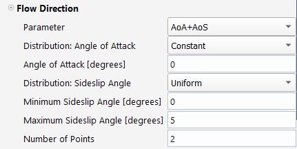
This setting defines the type of input parameter that will be used to define the flow direction. , and can be selected. This setting is only available for a . The Flow Direction is fixed to a 0 Angle of Attack [degrees] and Angle of Sideslip [degrees] when using a Domain Type.
Angle of attack (degrees) is used to define the flow direction for each design point. Increasing the angle of attack will increase the pitch of the aircraft with respect to the incoming flow.
Sideslip angle (in degrees) is used to define the flow direction for each design point. Increasing the sideslip angle will increase the yaw of the aircraft with respect to the incoming flow. If you would like to use a non-zero value for sideslip angle, you must ensure that you do not use a symmetry boundary to define their domain.
Both angle of attack and sideslip angle (in degrees) are used to define the flow direction for each design point. Increasing the angle of attack will increase the pitch of the aircraft with respect to the incoming flow. Increasing the sideslip angle will increase the yaw of the aircraft with respect to the incoming flow. If you would like to use a non-zero value for sideslip angle, you must ensure that you do not use a symmetry boundary to define their domain.
Distribution
This setting defines how the value of the input parameters selected above is distributed across each design point. , or can be selected. If the Parameter is set to , can also be selected. If the Parameter is set to , a Distribution setting is revealed and must be defined for both inputs. For example, in the image below, a distribution is used for angle of attack, and a distribution is used for the sideslip angle.
Refer to Using the Distribution Setting in Flight Conditions under Simulation Conditions for a more complete description of how this setting is used.
Parameter and Distribution Specific Input Values
Depending on what is selected for Parameter and Distribution, further inputs to control the values to use for the Flow Speed input parameter will be revealed under Flow Speed or in the Input Design Point table.
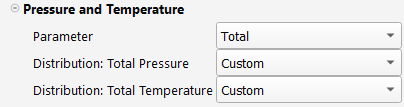
Pressure and Temperature
This section contains inputs to define the static pressure and temperature to perform your aerodynamic simulations. Settings applied in this section will be applied to the Inlet and Outlet boundary zones that are part of the or component groups.
Parameter
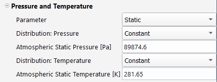
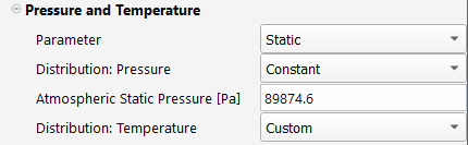
This setting defines the type of input parameters that will be used to define the static pressure and temperature at each design point. , , and can be selected.
Static Pressure [Pa] and Static Temperature [K] are directly used to define the condition at each design point.
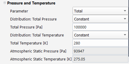
Total Pressure [Pa] and Total Temperature [K] are used to define the static pressure and static temperature of the condition for each design point. When selected, only number is available in the Flow Speed Parameter section.
The value computed for the Atmospheric Static Pressure [Pa] and Atmospheric Static Temperature [K] will be displayed in the Pressure and Temperature section of the Properties panel or in the Input Design Points table. Refer to the Air Properties section under Airflow Physics for more details about how the static temperature and the static pressure are computed from the total temperature, total pressure and Mach number.
For example, in the image below, both distributions are set to , and therefore the computed values of Static Pressure and Static Temperature are listed in grey in the Pressure and Temperature of the Properties panel.
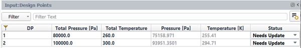
In the next example, both distributions are set to , and therefore the computed values of Static Pressure and Static Temperature are listed in grey inside the Input Design Points table.
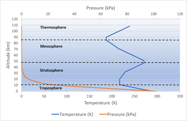
Using the International Standard Atmosphere, Flight Altitude [m] is used to define the Atmospheric Static Pressure [Pa] and Atmospheric Static Temperature [K] of the ambient flight conditions for each design point. Depending on each parameter’s Distribution setting, the value computed for the Atmospheric Static Pressure [Pa] and Atmospheric Static Temperature [K] will be displayed in the Pressure and Temperature section of the Properties panel or in the Input Design Points table.
Currently, this option is supported for the following atmospheric regions: Troposphere, Stratosphere, Mesosphere and Thermosphere, up to a maximum of 108,000 meters. Within these regions, static pressure and temperature are obtained using the correlations described in http://www.braeunig.us/space/atmmodel.htm.
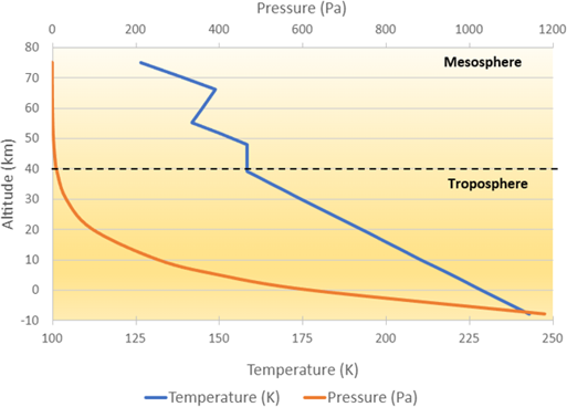
Mars Air Properties
Viking lander reentry profiles, covering altitudes from -1.49 to 120km, have been used to create analytical altitude profiles of pressure and temperature, as in http://www.braeunig.us/space/atmmodel.htm. As Mars lacks oceans to fill its lowest elevations, negative surface elevations exist. Therefore, the current implementation covers altitudes from -8km to 75km.
Using these analytical profiles, Flight Altitude [m] is used to define the Atmospheric Static Pressure [Pa] and Atmospheric Static Temperature [K] of the ambient flight conditions for each design point. Depending on each parameter’s Distribution setting, the value computed for the Atmospheric Static Pressure [Pa] and Atmospheric Static Temperature [K] will be displayed in the Pressure and Temperature section of the Properties panel or in the Input:Design Points table.
Note: The specific heat for CO2 and the species of is modeled by the nasa-9-polynomial correlations which consider the specific heat as a function of temperature. However, these correlations have a lower bound at T=200K. Since the static temperature at altitudes between 16 to 75 km is below 200K, the specific heat of all species including C02 is set to their lower bound.
Reynolds number is used to define the Atmospheric Static Pressure [Pa] and Atmospheric Static Temperature [K] of the ambient flight conditions for each design point. When is selected, Reynolds number and Atmospheric Static Temperature [K] should be specified in the Pressure and Temperature section and only Mach number is available inside the Flow Speed Parameter section.
The value computed for the Atmospheric Static Pressure [Pa] and Atmospheric Static Temperature [K] will be displayed in the Pressure and Temperature section of the Properties panel or in the Input Design Points table. Refer to the Air Properties section under Airflow Physics for more details about how the Atmospheric Static Pressure [Pa] is computed from Reynolds number and Atmospheric Static Temperature [K].
Distribution
This setting defines how the value of the input parameters selected above is distributed across each design point. , or can be selected. If the Parameter is set to , or , a Distribution setting is revealed and must be defined for multiple inputs. For example, in the image below, the Parameter is set to and a distribution is used for Pressure, and a distribution is used for Temperature.
Refer to Using the Distribution Setting in Flight Conditions under Simulation Conditions for a more complete description of how this setting is used.
Parameter and Distribution Specific Input Values
Depending on what is selected for Parameter and Distribution, further inputs to control the values to use for the Flow Speed input parameter will be revealed under Flow Speed or in the Input Design Point table.
Turbulence
This section contains inputs to define the inflow turbulence of your aerodynamic simulations. Settings in this section will be applied to the Inlet boundary zones that are part of the or component groups.
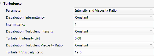
Parameter
This setting defines the turbulence specification method. , and can be selected.
Turbulent Intensity [%] and Turbulent Viscosity Ratio are used to define the inflow turbulence conditions. If a viscous turbulence model with Transition is selected, Intermittency will also be available. When the Spalart-Allmaras viscous model is selected, only Turbulent Viscosity Ratio will be available.
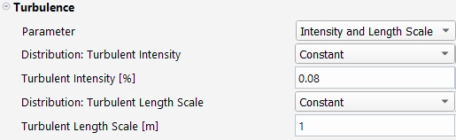
Turbulent Intensity [%] and Turbulent Length Scale [m] are used to define the inflow turbulence conditions. If a turbulence model with Transition is selected, Intermittency will also be available.
Note: When the viscous model is set to Reynolds Number Based, conditions specified for Intermittency, Turbulent Intensity [%] and Turbulent Viscosity Ratio or Turbulent Length Scale [m] are selectively applied. These conditions take effect only for design points using a viscous model that incorporates these turbulence parameters. For instance, in design points with laminar flows, none of the turbulence conditions specified will be applied, while Intermittency is exclusively applied to design points with a transition viscous model
Distribution
This setting defines how the value of the input parameters selected above is distributed across each design point. , or can be selected. If the Parameter is set to , a Distribution setting is revealed and must be defined for both inputs. For example, in the image below, distributions are used for both Turbulent Intensity [%] and Turbulent Length Scale [m].
Wall Conditions
This section contains inputs to define the conditions on all the wall zones if the option is enabled. By disabling this option, you are able to set different wall conditions for each wall inside the Component Groups step.
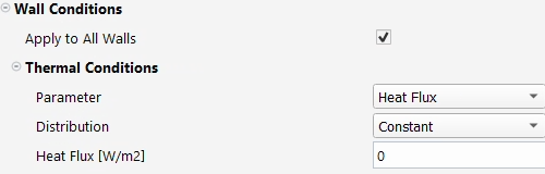
Note: Currently, only wall thermal conditions can be specified in Fluent Aero.
Thermal Conditions
Parameter
This setting specifies the thermal conditions method. and can be selected.
Distribution
This setting defines how the value of the input parameters selected above is distributed across each design point. , or can be specified. If the Parameter is set to , a Distribution setting of is revealed and must be defined. For example, in the image below, distribution is used for Temperature, and its value will be applied to all wall zones in all design points.

Custom Input and Output Parameters
This option allows the use of custom input parameters to vary at each design point. When this option is enabled, a window appears with a list of all custom inputs available. Select the Inputs you would like to use, and click . The selected input will appear as a fillable data column entry in the Input:Design Points table. If previous Results have already been created in your simulation, clicking will reset the custom input selection to be consistent to what was used in the previous results.

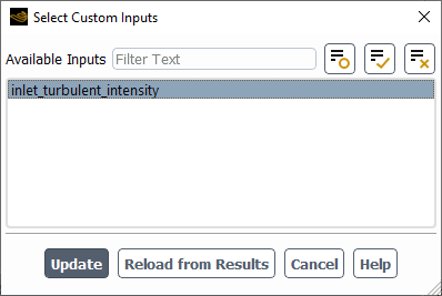
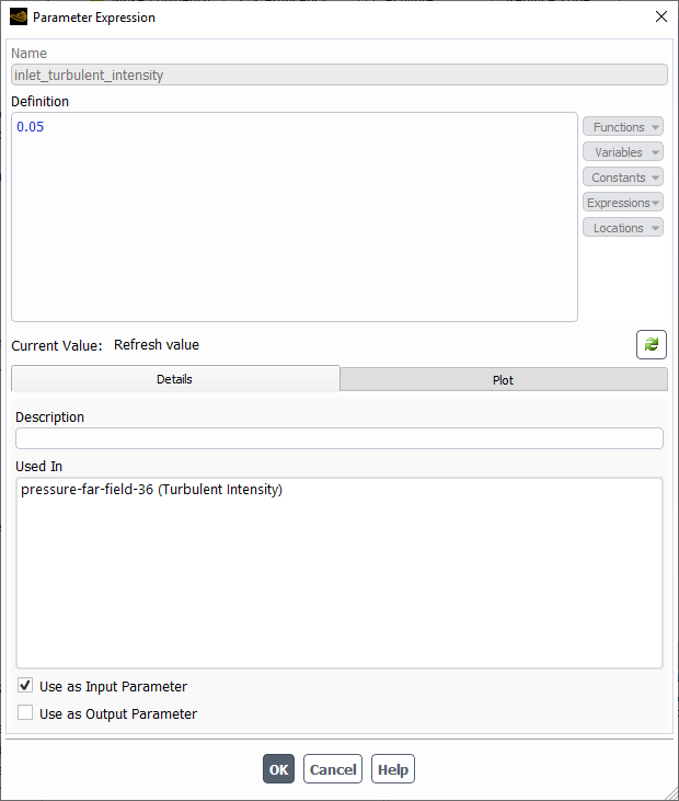
The list of custom input parameters will be filled by any input parameters defined in the initial case file using the Fluent Solution workspace’s parameter expression framework. If you would like to add another custom input parameter to your current Fluent Aero session, you can use the Workspaces → button to go to the Solution Workspace window and add new Parameter Expressions that are set to . The image below shows an example Parameter Expression defined in Fluent Solution workspace that works correctly as a custom input in Fluent Aero.
Customize Output Parameters
This option allows the use of custom output parameters to vary at each design point. When this option is enabled, a window appears with a list of all custom outputs available. Select the outputs you would like to use, and click . When your Results are calculated, a custom output table will be produced listing the value of each selected custom output for each design point. If previous Results have already been created in your simulation, clicking will reset the custom output selection to be consistent to what was used in the previous results.

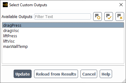
The list of custom output parameters will be filled with both the custom outputs available in Fluent Aero by default, and by any output parameters defined in the initial case file using the Fluent Solution workspace’s Parameter Expression framework. The following default custom outputs are available in Fluent Aero:
dragPress
The pressure component of the total drag force.
dragVisc
The viscous component of the total drag force.
liftPress
The pressure component of the total lift force.
liftVisc
The viscous component of the total lift force.
maxWallTemp
The maximum wall temperature that occurs on all walls in the domain.
If you would like to add another custom output parameter to your current Fluent Aero session, you can use the button to go to the Solution workspace window and add new Parameter Expressions that are set to .
Input:Design Points Table
When you modify the settings of Simulation Conditions, an Input: Design Points table will be generated in the top-right area of the Fluent Aero user interface and modified to match the settings you have selected. This table will consist of a row for each design point you have requested to update, and a column for each input parameter that will be varied. In this table, the first column lists the design point number, the middle columns list the variable input parameters, and the last column list the Status of each design point calculation. The input variables in the middle columns can be edited by double clicking a cell and entering a value. The Status of the final column can be changed by selecting an item from the drop down list. In the image below, there are 5 design points that feature a range of input Pressure and Temperature values and each Design Point Status is currently set to , signifying that these design points have not yet been updated.

Design Point Status
The Status column of the Input:Design Point table is an important way of assessing and interacting with the calculation of each design point. This column enables you to check if a design point has been updated successfully or not, and to request changes to the design point calculation. The following design point statuses are possible:
The Status will be set to when either:
The design point has not yet been updated.
A setting in the Geometric Properties, Airflow Physics, Simulation Conditions or Component Groups steps has changed since the last time the design point has been updated, or
The input values used in the Input:Design Points table have changed since the last time the design point has been updated.
Notably, changes to the Solve step will not cause the Status to change to . This is because you may want to change the Solve settings midway through a design point calculation before continuing with the calculation.
Lastly, you can manually set a Design Point Status to , even if the above mentioned settings have not been changed.
Any Design Point whose Status is set to will be updated when you click the command, and any previous solutions that may have existed for that design point will not be used.
The Status will be set to when a design point has been updated successfully, and a solution has been obtained.
Any Design Point whose Status is set to will not be updated when you click the command.
The Status will be set to if you have used the command during the calculation of a design point.
Any Design Point whose Status is set to will not be updated when you click the command.
Note: When a design point calculation is interrupted, by default, the results files (out.0*.dat[.h5] and out.0*.cas[.h5]) are not saved, and the values in the results tables (Table:Summary, Table:Coefficients, Table:Residuals) are not updated. If you would like to save your current solution to the results files and update the results tables, the command should be used.
The Status will be set to if an error occurs during the calculation of a design point that causes the calculation to stop.
Any Design Point whose Status is set to will not be updated when you click the command.
Note: If you experience an error during calculation, the Console output, or the .trn file located in the simulation folder, can be investigated to find more information on the cause of the error.
You can set the Status of a Design Point to when you do not want to update a given design point after clicking the command.
You can set the Status to if you would like to continue the calculation of a previously updated design point. Any Design Point whose Status is set to will load and continue calculating from the previous solution file (out.0*.dat[.h5]) when you click the command.
Set the Status of a Design Point to to only initialize the solution at a given design point after pressing .
Any Design Point whose Status is set to will be initialized and no solver iterations will be performed. This allows you to investigate the Initial solution of a design point before continuing on with the full calculation.
The Status will be set to when a design point has been initialized successfully, and an initial solution has been obtained.
Any Design Point whose is set to will continue to be calculated from the current initial solution when you click .
Commands Available from Simulation Conditions
A number of commands are available from the Simulation Conditions step. These can be accessed either from the buttons at the bottom of the Properties panel, or by right-clicking Simulation Conditions in the Outline View panel. Most of these commands are used to interact with the Input Design Points table.
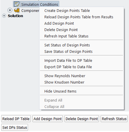
This command can be used to generate the Input: Design Points table in the top-right area of the Fluent Aero user interface. Typically, this table is generated automatically, however, this option can be used if the table is not generated as expected.
or
If Results have already been computed for your simulation, this command will reload the design point table values from the previously generated results, thereby removing any changes that may have been made by yourself.
This command will add a design point to the bottom of the Input: Design Points table.
This command will delete a design point from the Input:Design Points table. A panel will appear, allowing you to enter the Design Point Number that you would like to delete. The design point will then be removed from the table.
If previous results have been calculated, all files associated with that design point and listed in the DP-# folder shown in the Project View will be deleted (including .cas, .dat and .fconverg files, as well as any .csv plot files that were generated). The numbering of all other design point folders and files will be readjusted such that they remain sequential. For example, if the previous Results included three design point folders (DP-1, DP-2 and DP-3), and Design Point 2 is deleted, the previous DP-2 folder and all its contents will be removed, and the previous DP-3 folder will be renamed to DP-2 to ensure that sequential numbering of folders and files is maintained.
or
This command will refresh the Status of each Design Point to the value that was obtained at the end of your most recent calculation, or to if no calculation has been performed, thereby removing any changes that may have been made by yourself.
Set DPs Status or Set Status of Design Points
This command can be used to set the Status of a group of Design Points and also appears in the ribbon of Fluent Aero under Design Points. For more information regarding this command, consult Status under Ribbon Commands.
This command can be used to save the status of a group of design points. When selected, the currently selected Status of each Design Point in the Input: Design Points table will be saved. Use this command to force certain design points to be set to . Since the status will be saved, you are required to update the design point again to get the status back to .
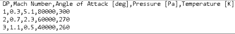
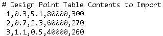
This command can be used to fill the contents of your Input:Design Points table by importing a comma separated value (.csv) file. The first row of this file should contain a header line, which should either start with a comma separated list of the variables used in the file or start with a # comment symbol followed by a brief description of the contents of the file. The remaining rows should contain the design point number and all values you would like to fill in the table, separated by commas. These variable values should all exist in your Input:Design Points table, after you have set the variables of interest to . All variables should be in SI units.
If you have included a comma separated list of variables in the header (as shown in the figure below), the values will be imported into the appropriate column.
If only a comment line was used (as shown in the figure below), the values will be imported sequentially in order of appearance. For example, if Mach, AoA, Static Pressure and Static Temperature are all set to , the order of each line of the file should be:
This command can be used to export the contents of your Input:Design Points table to a comma separated values (.csv) file.
/
These commands allow you to show or hide the Knudsen Number column in the Input:Design Points table. The Knudsen Number column will automatically appear when the Knudsen number of any design point exceeds the Knudsen Number Criterion (Transitional Regime Threshold) and cannot be hidden. The Knudsen number is highlighted in orange for transitional regime (Transitional Regime Threshold<=Kn<0.2) and in red for free molecular regime (Kn>=0.2).
/
These commands allow you to show or hide the column in the table. The column will automatically appear when the Reynolds number is an input parameter or when the is set as viscous model. In the latter case, the Reynolds number is blue for laminar flows and green for transition flows. For fully turbulent flows, the color used follows the standard rule of any other parameter of the Design Point Table.
Once the matrix of conditions have been specified, you can continue to the next step.
In this step, two important setup tasks are performed:
The boundary zones of the geometry and mesh can be organized into groups of zones that represent entire aircraft components. This allows you to focus more on interacting with the aircraft geometry, rather than interacting with an unorganized list of boundary zones. It can help facilitate simulation setup and post processing. For example, an engine intake, exhaust and nacelle wall boundaries can be organized into an Engine Component.
Any boundary zone or component specific boundary conditions can be applied. For example, the engine exhaust mass flow, which may change per design point, can be setup.
For simple geometries, where no organization of boundary zones is required, this step is not required and can be skipped.
Note: It is highly recommended to ensure the organization of Component Groups and the selection of boundary zones names and types is completed before calculating any design point. If changes are made to any boundary zone type or boundary zone name after any Results have been calculated, this will be registered as a substantial change to the setup of the simulation, and the Status of all design points will be set to . Furthermore, the run.settings file, which stores the component specific boundary condition setup, will be deleted. After this, a command or command must be performed so that an updated run.settings file is saved.
The first setup task that the Component Groups step is capable of is to organize the boundary zones of the geometry into groups of zones that represent aircraft components. Organizing boundary zones in this way will make interacting with the geometry and mesh more intuitive during setup and post processing.
Default Component Groups
By default, there are at least two Component Groups present when you first creating a new simulation. They are:
A Freestream or WindTunnel group that should contain all external boundaries of your computational mesh. This group is either automatically detected and setup when you first connect to your case file, or is modified and created manually. Refer to Freestream or WindTunnel Domain Type Requirements for more details.
An Other group that should contain all other boundaries.
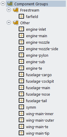
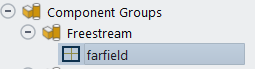
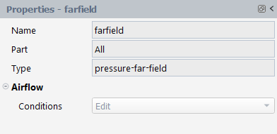
The image below shows an example of Freestream Domain Type setup where the pressure-far-field type zone called farfield is part of the Freestream group and all other walls are part of the Other group.
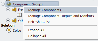
Further organization of these boundaries can be done by right-clicking the Component Groups step and by using the Component Manager panel.
Using the Boundary Zone Right-Click Commands
The following boundary zone organization commands are available by right-clicking a boundary in the Component Groups list.
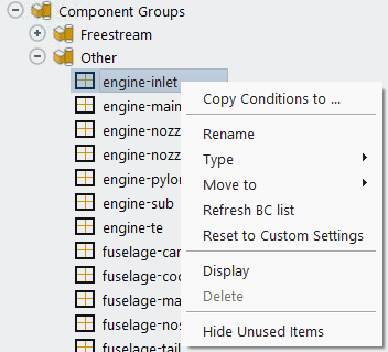
Copy boundary conditions from one zone to other zones of the same type.
Renames the selected boundary. This is only available for boundaries in the Other group.
Allows you to change the boundary type of the selected boundary. It is only possible to change the Type of a boundary zone when it is inside the Other group.
Allows you to move the selected boundary to another Component Group.
This command will refresh the boundary list. This should update the Fluent Aero’s boundary conditions list if any boundaries have been changed from inside the Fluent Solution workspace.
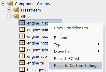
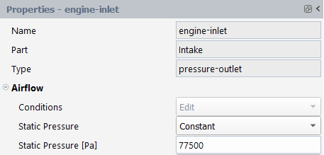
If the Conditions setting of a boundary zone is set to mode, this command will change the Conditions setting back to . This allows you to go to the Fluent Solution workspace, and enter custom settings to the zone. This process is shown in the images below.
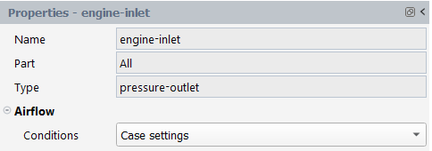
In this example, the Conditions setting of the engine-inlet boundary zone is currently set to , and Constant value of Static Pressure applied.
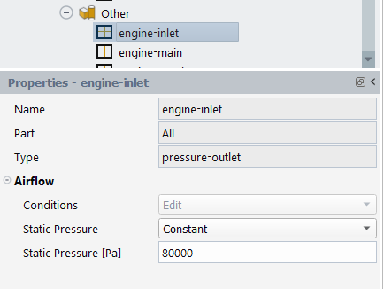
You can right-click the engine-inlet zone and select to change the Conditions setting to Case settings.
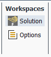
Next, you can go to the Fluent Solution workspace using the Workspaces → button in the Project ribbon.
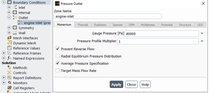
From the Solution workspace window that appears, you can change the engine-inlet boundary conditions to any custom settings that are required for the simulation. Since the engine-inlet Conditions is set to , Fluent Aero will use the settings that are defined in the Solution workspace when calculating the solution.
Note: Once the Conditions is set to in the Properties panel, the setting can no longer be changed from the Properties panel. Instead, as described above, you must use the command to change the setting back to . However, because the setting was previously set to , the conditions may have been updated. Go to the Solution workspace and verify the intended settings are used on that boundary before proceeding with the calculation.
Displays the selected boundary in the Graphics panel.
Manage Components Using the Component Manager
The Component Manager panel can be used to create groups of components and reorganize boundary zones into these groups. It can be accessed by clicking the command button at the bottom of the Properties – Components Groups panel, or by right-clicking Component Groups and selecting .

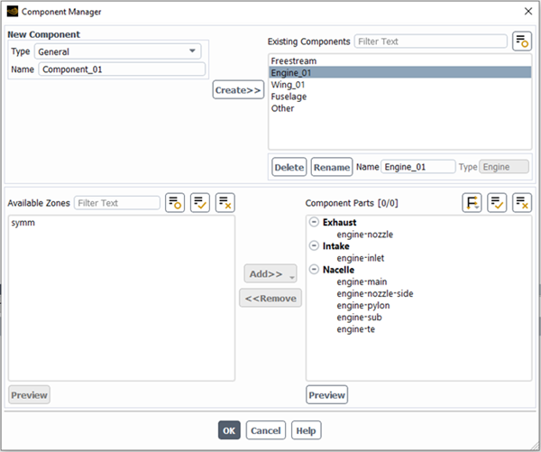
After selecting the command, a Component Manager panel will appear. There are four main areas of the Component Manager:
New Component (top-left), which contains options to create a new component, including selecting the Type and setting the Name of the new component.
Existing Components (top-right), which contains a selectable list of existing components, as well as commands to Delete or Rename existing components.
Available Zones (bottom-left), which shows a selectable list of zones that can be added to a component using the button.
Component Parts (bottom-right), which shows the list of zones that are contained within the currently selected Existing Component to. Depending on the type of component selected, this list of zones will be organized into specific Component Parts that only allow specific boundary types. Zones can be removed from a component group by selecting the zone in Component Parts and using the button.
The image below shows the Component Manager panel after it has been used to setup , and components in addition to the Freestream and Other components that are listed by default. A complete walk through of how to set up the components can be found in Introduction to Aircraft Component Groups and Computing Aerodynamic Coefficients on an Aircraft at Different Flight Altitudes and Engine Regimes.
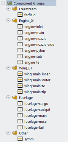
The image below shows the corresponding Outline View list of Components, after the Component Manager was used to organize the boundary zones.
Types of Components
Currently, there are three available Types of Components, , and .
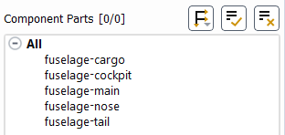
A type component has no specific requirements. It features a single component part called , to which any type of Fluent Aero supported boundary zone can be added.
The Component Parts of the type component called fuselage from the example above is shown in the image below:
A type component contains the following Component Parts with the following requirements:
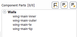
Walls: this component part must contain wall type boundary zones.
The Component Parts of the type component called from the example above is shown in the image below:
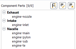
An type component contains the following Component Parts with the following requirements:
Exhaust: This component part must contain a mass-flow-inlet or pressure-inlet type boundary zone.
Intake: This component part must contain a pressure-outlet or mass-flow-outlet type boundary zone.
Nacelle: This component part is not required but may only have wall -type boundary zones.
The Component Parts of the type component called engine-01 from the example above is shown in the image below:
The second setup task that the Component Groups step is capable of is to apply specific boundary conditions to component zones.
While the Simulation Conditions step is used to apply Freestream or WindTunnel Inlet and Outlet conditions that represent flight or wind tunnel conditions of the aircraft, the zone specific boundary conditions of a Component Groups allows you to apply boundary conditions onto aircraft components. These boundary conditions may be constant or varying (custom) for each design point simulation. The mass flow rate of the engine exhaust is an example of a type of boundary condition that will be applied in the Component Groups step.
The zone specific boundary conditions setup options provided in the Component Groups step is only available on Fluent Aero’s supported boundary types and only for certain supported boundary variables. To setup zone specific boundary conditions on unsupported boundaries, the functionality provided by the Simulation Conditions step can be used.
Zones using a type that is directly supported from inside Fluent Aero’s user interface will appear with a black square with gold cross icon next to its zone name inside.

The following boundary zone types are supported by Fluent Aero.
Inlets
(special case – only supported as part of the group)
(special case – only directly supported as part of the group)
Outlets
Other Boundary Types
For some supported zone type, Fluent Aero may display some common boundary variables that can be controlled directly from inside Fluent Aero.
Note: To control any variable that is not displayed directly from inside Fluent Aero, use the Workspaces → button to show the Fluent Solution workspace and modify the setting there, and/or use the Simulation Conditions → functionality to modify the variable per design point.
Inlets
In this section, the settings available in Fluent Aero of supported inlet boundary zones are described.
Note: All the supported inlets that are not part of the or group have the same Turbulence Specification and Mass Fractions setting options which are described at the end of the current section. For inlets in the or group, the turbulence and mass fractions settings will not be displayed in its properties panel as they are defined in the Simulation Conditions step.
Mass-flow-inlet
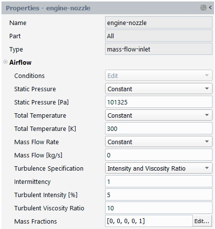
Conditions
Setting Conditions to will cause Fluent Aero to reveal the list of settings available. Setting Conditions to will cause Fluent Aero to use the zone settings that were setup in the initial case file or from within the Fluent Solution workspace.
Note: If Conditions is set to in the panel, its setting can no longer be modified from the panel. Instead, you must use the command to change the setting back to . However, because the setting was previously set to , the conditions may have been updated. Go to the Solution workspace and verify that the intended settings are used on that boundary before proceeding with the calculation.
Static Pressure
Set the Static Pressure specification method to either , or . Setting to allows you to specify a constant value that will be used in all design points.
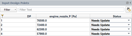
Setting to inserts an extra column in the Input: Design Points table where a custom static pressure can be specified for each design point, as shown below.
Setting to Case settings will force Fluent Aero to use the Static Pressure setting that is defined in the initial case file or from within the Fluent Solution workspace.
Static Pressure [Pa]
Sets a constant pressure in Pascal to use on this boundary condition for all design points.
Parameter Name (Static Pressure)
If Static Pressure is set to , this option is revealed. In this case, you can set the name of the custom variable that is used to control the static pressure of the mass flow inlet zone. The default name of the expression uses the following format: zone_name_P.
Total Temperature
Set the Total Temperature specification method to either , or . Setting to allows you to specify a constant value that will be used in all design points.
Setting to inserts an extra column in the Input: Design Points table where a custom total temperature can be specified for each design point.
Setting to Case settings will allow Fluent Aero to use the Total Temperature setting that is defined in the initial case file or from within the Fluent Solution workspace.
Total Temperature [K]
Sets a constant total temperature in Kelvin to use on this boundary condition for all design points.
Parameter Name (Total Temperature)
If Total Temperature is set to , this option is revealed. In this case, you can set the name of the custom variable that is used to control the total temperature of the mass flow inlet zone. The default name of the expression uses the following format: zone_name_T0.
Mass Flow Rate
Set the Mass Flow specification method to either , or .
Setting to allows you to specify a constant value that will be used in all design points.
Setting to inserts an extra column in the Input: Design Points table where a custom mass flow can be specified for each design point.
Setting to will force Fluent Aero to use the Mass Flow Rate setting that is defined in the initial case file or from within the Fluent Solution workspace.
Mass Flow [kg/s]
Sets a constant mass flow in kilograms per second to use on this boundary condition for all design points.
Parameter Name (Mass Flow)
If Mass Flow is set to , this option is revealed. In this case, you can set the name of the custom variable that is used to control the mass flow of the mass flow inlet zone. The default name of the expression uses the following format: zone_name_massflow.
Turbulence Specification
The Turbulence Specification options are common to all inlet boundary conditions that are not in the or group. For more details, see Turbulence Specification at Inlets at the end of the current Inlets section under Boundary Zone Types Supported by Fluent Aero.
Mass Fractions
When a mixture is selected in Air Properties, mass fractions for each species can be applied. This setting is common to all inlet boundary conditions that are not in the or group. For more details, see Mass Fractions at Inlets at the end of the current Inlets section under Boundary Zone Types Supported by Fluent Aero.
Mass-flow-inlet settings that may be automatically setup by Fluent Aero
When a mass-flow-inlet boundary is used, Fluent Aero may automatically setup some background settings which are not shown directly in Fluent Aero, but can be seen from the background Solution workspace session:
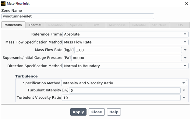
If the mass-flow-inlet is a member of the WindTunnel group, Mass Flow Specification Method will be set to and Direction Specification Method will be set to .
The example image below shows the background Solution workspace settings of an example mass-flow-inlet boundary called windtunnel-inlet that is part of a WindTunnel type group.
Note: The Mass Flow Specification Method is set to and the Direction specification Method is set to , as described above.
Pressure-inlet
Conditions
Setting Conditions to will cause Fluent Aero to reveal the list of settings available that you can directly specify inside the properties panel. Setting Conditions to will cause Fluent Aero to use the zone settings that were setup in the initial case file or from within the Fluent Solution workspace.
Note: If Conditions is set to in the Properties panel, its setting can no longer be modified from the Properties panel. Instead, you must use the command to change the setting back to . However, because the setting was previously set to , the conditions may have been updated. Go to the Solution workspace and verify the intended settings are used on that boundary before proceeding with the calculation.
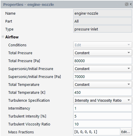
Total Pressure
Set the Total Pressure specification method to either , or .
Setting to allows you to specify a constant value that will be used in all design points.
Setting to will insert an extra column in the Input: Design Points table where a custom total pressure can be specified for each design point, as shown in the image below.
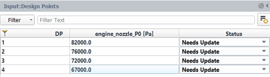
Setting to will force Fluent Aero to use the Total Pressure setting that is defined in the initial case file or from within the Fluent Solution workspace.
Total Pressure [Pa]
Sets a constant total pressure in Pascal to use on this boundary condition for all design points.
Parameter Name (Total Pressure)
If Total Pressure is set to , this option is revealed. In this case, you can set the name of the custom variable that is used to control the total pressure of the pressure inlet zone. The default name of the expression uses the following format: zone_name_P0.
Supersonic/Initial Pressure
Set the Supersonic/Initial Pressure specification method to either , or .
Setting to allows you to specify a constant value that will be used in all design points.
Setting to will insert an extra column in the Input: Design Points table where a custom supersonic/initial pressure can be specified for each design point.
Setting to will force Fluent Aero to use the Supersonic/Initial Pressure setting that is defined in the initial case file or from within the Fluent Solution workspace.
Supersonic/Initial Pressure [Pa]
Sets a constant supersonic/initial pressure in Pascal to use on this boundary condition for all design points.
Parameter Name (Supersonic/Initial Pressure)
If Supersonic/Initial Pressure is set to , this option is revealed. In this case, you can set the name of the custom variable that is used to control the static pressure of the pressure inlet zone. The default name of the expression uses the following format: zone_name_P.
Total Temperature
Set the Total Temperature specification method to either , or .
Setting to allows you to specify a constant value that will be used in all design points.
Setting to will insert an extra column in the Input: Design Points table where a custom total temperature can be specified for each design point.
Setting to will force Fluent Aero to use the Total Temperature setting that is defined in the initial case file or from within the Fluent Solution workspace.
Total Temperature [K]
Sets a constant total temperature in Kelvin to use on this boundary condition for all design points.
Parameter Name (Total Temperature)
If Total Temperature is set to , this option is revealed. In this case, you can set the name of the custom variable that is used to control the total temperature of the mass flow inlet zone. The default name of the expression uses the following format: zone_name_T0.
Turbulence Specification
The Turbulence Specification settings options are common to all inlet boundary conditions that are not in the or group. For more details, see Turbulence Specification at Inlets at the end of the current Inlets section under Boundary Zone Types Supported by Fluent Aero.
Mass Fractions
When a mixture is selected in Air Properties, mass fractions for each species can be applied. This setting is common to all inlet boundary conditions that are not in the or group. For more details, see Mass Fractions at Inlets at the end of the current Inlets section under Boundary Zone Types Supported by Fluent Aero.
Pressure-far-field (special case – only supported as part of the group)
A pressure-far-field type boundary is only supported by Fluent Aero when it is used as part of the group.
Conditions
Fluent Aero will automatically set Conditions to and automatically apply the far-field conditions defined inside the Simulation Conditions step for each design point.
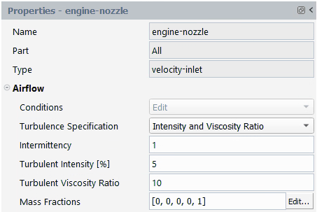
Velocity-inlet (special case – only directly supported as part of the group)
A velocity-inlet type boundary is only directly supported by Fluent Aero when it is used as part of the group, specifically to define the Inlet boundary. If a velocity-inlet type boundary is used outside of a group, only the Turbulence Specification settings can be defined from Fluent Aero. Other settings cannot be set from Fluent Aero and their settings in the Solution workspace will be applied.
Conditions
Setting Conditions to will cause Fluent Aero to reveal the list of settings available to specify directly inside the properties panel.
Turbulence Specification
The Turbulence Specification settings are common to all inlet boundary conditions that are not in the or group. For more details, see Turbulence Specification at Inlets at the end of the current Inlets section under Boundary Zone Types Supported by Fluent Aero.
Mass Fractions
When a mixture is selected in Air Properties, mass fractions for each species can be applied. This setting is common to all inlet boundary conditions that are not in the or group. For more details, see Mass Fractions at Inlets at the end of the current Inlets section under Boundary Zone Types Supported by Fluent Aero.
Turbulence Specification at Inlets
Turbulence conditions can be specified at the inlets that are not in the or group of the computational domain.
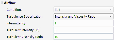
Three options are available: , and . When loading a case file that contains constant values of Turbulent Intensity [%], Turbulent Viscosity Ratio or Turbulent Length Scale and Intermittency (available when a turbulence model with transition is used), the Turbulence Specification method will be automatically set to or and their values are automatically copied to Fluent Aero. Only the following turbulence models are currently supported during the import: k-Omega SST (without transition model), k-Omega WJ-BSL-EARSM (Beta) (without transition model), Transition SST and K-Omega SST Intermittency Transition and Spalart-Allmaras. If any of the above-mentioned conditions are not satisfied, Fluent Aero will set the Turbulence Specification method to and the turbulence settings in the case file will be used.
If you change to Intensity and Viscosity Ratio or Intensity and Length Scale from Fluent Aero, then Turbulent Intensity [%] and Turbulent Viscosity Ratio or Turbulent Length Scale [m] can be set from Fluent Aero and will be applied to the Solution workspace if the Turbulence model is not set to . If the Spalart-Allmaras model is selected, only can be specified under . Only constant values can be set from the boundary conditions properties panel in Fluent Aero. However, it is possible to use , located under Simulation Conditions, to add an equation to describe the turbulence condition at the farfield or the wind tunnel inlet.
When the viscous model is set to Reynolds Number Based, conditions specified for Intermittency, Turbulent Intensity [%] and or Turbulent Length Scale [m]are selectively applied. These conditions take effect only for design points using a viscous model that incorporates these turbulence parameters. For instance, in design points with laminar flows, none of the turbulence conditions specified will be applied, while Intermittency is exclusively applied to design points with a transition viscous model.
Mass Fractions at Inlets
When a mixture is selected for Air Properties, Mass Fractions condition can be specified at the inlets that are not in the or group of the computational domain.
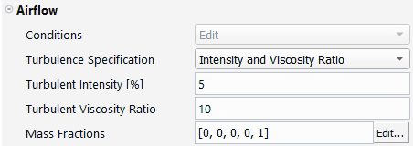
To modify the Mass Fractions, click on the button beside the Mass Fractions display box. A new panel will open where you can set the mass fraction for each species, and the mass fraction of the last species will be computed automatically. Note that constant mass fractions will be applied to all design points and the sum of species’ mass fractions must equal one.
Outlets
In this section, the settings available in Fluent Aero of the supported outlet boundary conditions are described.
Pressure-outlet
Conditions
Setting Conditions to will cause Fluent Aero to reveal the list of settings available to specify directly inside the properties panel. Setting Conditions to will cause Fluent Aero to use the zone settings that were setup in the initial case file or from within the Fluent Solution workspace.
Note: If Conditions is set to in the Properties panel, its setting can no longer be modified from the Properties panel. Instead, you must use the command to change the setting back to . However, because the setting was previously set to , the conditions may have been updated. Go to the Solution workspace and verify the intended settings are used on that boundary before proceeding with the calculation.
Static Pressure
Set the Static Pressure specification method to either , or .
Setting to allows you to specify a constant value that will be used in all design points.
Setting to will insert an extra column in the Input: Design Points table where a custom static pressure can be specified for each design point.
Setting to will force Fluent Aero to use the Static Pressure setting that is defined in the initial case file or from within the Fluent Solution workspace.
Static Pressure [Pa]
If the Static Pressure specification method is set to , a constant pressure in Pascal should be specified on this boundary condition for all design points.
Parameter Name (Static Pressure)
If the Static Pressure specification method is set to , several options appear. In this case, you can set the name of the custom variable that is used to control the static pressure of the pressure-outlet zone. The default name of the expression uses the following format: zone_name_P.
Pressure-outlet settings that may be automatically setup by Fluent Aero
When a pressure-outlet boundary is used, Fluent Aero may automatically setup some background settings which are not shown directly in Fluent Aero, but can be seen from the background Solution workspace session:
If Conditions is set to or :
will be enabled, will be enabled.
If the Solver Type is set to and the pressure-outlet is a member of the or group, the Averaging Method will be set to .
If the Solver Type is set to and the pressure-outlet is not a member of the or group, the Averaging Method will be set to .
If Conditions is set to
No automatic setup is done to the pressure-outlet settings.
The example image below shows the background Solution workspace settings of an example pressure-outlet boundary called engine-intake that is part of an Engine type group, used in a Density based solver type calculation, with a custom input for the pressure value. In the image below, see that is enabled and the is enabled, with Averaging Method set to , as described above.
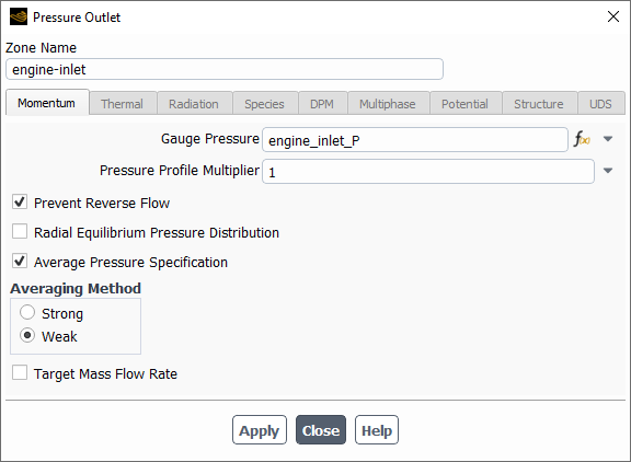
Mass-flow-outlet
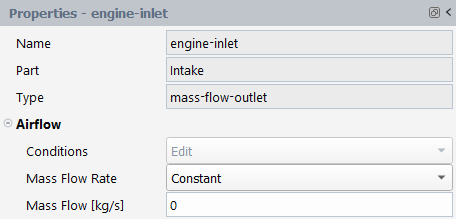
Conditions
Setting Conditions to will cause Fluent Aero to reveal the list of settings available to specify directly inside the properties panel. Setting Conditions to will cause Fluent Aero to use the zone settings that were setup in the initial case file or from within the Fluent Solution workspace.
Note: Once the Conditions is set to in the Properties panel, the setting can no longer be changed from the Properties panel. Instead, you must use the command to change the setting back to . However, because the setting was previously set to , the conditions may have been updated. Go to the Solution workspace and verify the intended settings are used on that boundary before proceeding with the calculation.
Mass Flow
Set the Mass Flow specification method to either , or .
Setting to allows you to specify a constant value that will be used in all design points.
Setting to will insert an extra column in the Input: Design Points table where a custom mass flow can be specified for each design point.
Setting to will force Fluent Aero to use the mass flow rate setting that is defined in the initial case file or from within the Fluent Solution workspace.
Mass Flow [kg/s]
Sets a constant mass flow in kilograms per second to use on this boundary condition for all design points.
Parameter Name (Mass Flow)
If Mass Flow is set to , this option is revealed. In this case, you can set the name of the custom variable that is used to control the mass flow of the mass flow inlet zone. The default name of the expression uses the following format: zone_name_massflow.
Other Boundary Types
Wall
If the option is disabled in the Simulation Conditions step, you will be able to customize wall conditions on each individual wall.
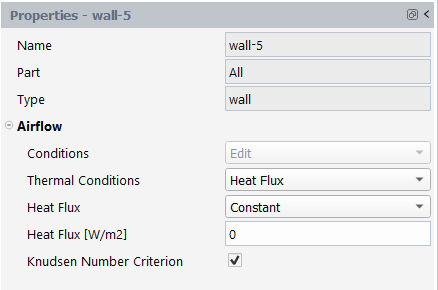
Conditions
Setting Conditions to will cause Fluent Aero to reveal the list of settings available to specify directly inside the properties panel. In the current version of Fluent Aero, only certain thermal conditions and Knudsen number related conditions can be specified. Moreover, momentum conditions specified in the case file will not be modified. Setting Conditions to will cause Fluent Aero to use the zone settings that were setup in the initial case file or from within the Fluent Solution workspace.
Note: Once Conditions is set to in the Properties panel, the setting can no longer be changed from the Properties panel. Instead, you must use the command to change the setting back to . However, because the setting was previously set to , the conditions may have been updated. Go to the Solution workspace and verify the intended settings are used on that boundary before proceeding with the calculation.
Thermal Conditions
Select the type of Thermal Conditions to apply: , or . If is selected, the thermal conditions defined in the initial case file, or from the Solution workspace window will be applied.
Heat Flux
This option appears if Thermal Conditions is set to . The specification method for can be either , or .
Setting to allows you to specify a constant value that will be used in all design points.
Setting to will insert an extra column in the Input: Design Points table where a custom mass flow can be specified for each design point.
Setting to will force Fluent Aero to use the heat flux setting that is defined in the initial case file or from within the Fluent Solution workspace.
Heat Flux [W/m2]
Sets a constant heat flux to use on this boundary condition for all design points.
Parameter Name (Heat Flux)
If Heat Flux is set to , this option is revealed. In this case, you can set the name of the custom variable that is used to control the heat flux of the wall zone. The default name of the expression uses the following format: zone_name_q.
Temperature
This option appears if Thermal Conditions is set to . The specification method for can be either , or . Setting to allows you to specify a constant value that will be used in all design points. Setting to will insert an extra column in the Input: Design Points table where a custom mass flow can be specified for each design point. Setting to will force Fluent Aero to use the temperature setting that is defined in the initial case file or from within the Fluent Solution workspace.
Temperature [K]
Sets a constant temperature to use on this boundary condition for all design points.
Parameter Name (Temperature)
If Temperature is set to , this option is revealed. In this case, you can set the name of the custom variable that is used to control the temperature of the wall zone. The default name of the expression uses the following format: zone_name_T.
This option is only available when in Airflow Physics is enabled. If this option is unchecked, no-slip condition will replace the partial slip condition on the current wall for design points with a Knudsen number above the specified threshold. Otherwise, partial-slip wall conditions will prevail.
Symmetry
No settings are available for boundary zones of symmetry type.
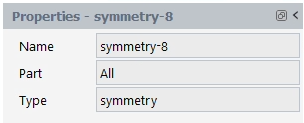
Periodic
Periodic boundaries can be used in Fluent Aero. However, they must be setup inside the Fluent Solution workspace.
Zones using a type that is not directly supported inside Fluent Aero’s UI will appear with a grey square icon next to its zone name inside.

Also, a note will appear in the Properties panel specifying that the zone is not yet supported, along with recommendations on how to modify the input values on this boundary zone type, if needed.
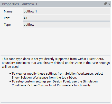
For any zone type that is not directly supported by Fluent Aero, the boundary conditions that are already defined on this zone in the case settings will be used. If you would like to modify these settings, you can do so by selecting the Workspaces → button from the top ribbon. Furthermore, to setup custom settings per design point, the Simulation Conditions → functionality can be used.
The final setup task that the Component Groups step is capable of is to enable component specific output parameters. This allows you to collect certain standard outputs from different Component Groups, depending on their type.
Manage Outputs
The Manage Component Outputs panel can be used to enable component specific output parameters, depending on what you may require for post processing. It can be accessed by clicking at the bottom of the Properties – Components Groups panel, or by right-clicking Component Groups and selecting .
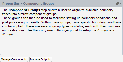
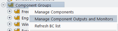
After selecting the command, a Manage Component Outputs panel will appear.
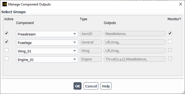
A row will appear for each Component listed in your Component Groups step. The following options are available:
Active
Enable this option to cause the component specific outputs to be shown for that component.
Component
The name of the component.
Type
The component type.
Outputs
A list of component specific outputs that will be generated if active for that component. Each Type of Component features a different list of available component outputs that can be selected. The following default outputs are available:
Type Component
: The mass balance of the airflow taking into account the Freestream or WindTunnel velocity-inlet boundaries that define the external boundaries of the domain.
Type Component
: the total Lift force acting upon the component.
: the total Drag force acting upon the component.
Type Component
: the total Lift force acting upon the component.
: the total Drag force acting upon the component
Type Component
: the thrust vector produced by the engine group. The following equation is used to compute each component of the thrust of the engine group:
Note: Currently, the pressure contribution is not included in the thrust calculation.
: the mass balance of airflow taking into account the engine inlet and exhaust boundaries
Enable this option to cause the component specific outputs to be monitored so that they can be tracked in the Convergence panel.
Once the solution has been calculated, if any Component Outputs are Active, the values of the Component Outputs will be listed in the Table:Component Outputs
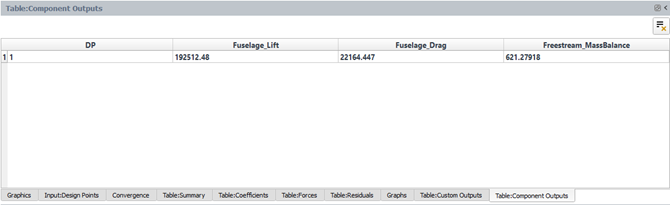

The Files step is used to select the output files to be written per design point. For each design point, a user can select to write the final case and solution files, intermediate solution files and extra post processing files. However, the more files that are written will increase the amount of disk space consumed, especially for project for project with many design points. By default, only Write Case Files and Write Solution Files is enabled, which causes an out.000#.cas.h5 and out.000#.dat.h5 to be written for each design point.
Note:For reduced disk space consumption and easier file organization after a run is completed, it may be helpful to archive your Fluent Aero project using your operating system’s archiving tools (like zip and tar). See Project Archiving and Disk Space Management for recommendations on how to archive your project and on which files can be removed to preserve space.
Clicking Files will reveal the Properties - Files window.
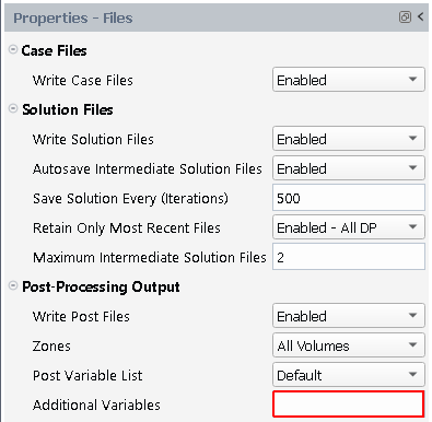
Case Files
Write Case Files
If this setting is , Fluent Aero will write case files (out.000#.cas.h5) for each design point. These files will be shown inside the DP-* folders in the Project View. While these case files are not necessary to launch a Fluent Aero simulation, they may be useful if you want to load and recall the exact case settings used for each design point, or if you would like to export and use this case file in a separate calculation inside the Fluent Solution workspace.
Solution Files
Write Solution Files
If this setting is , Fluent Aero will write solution files (out.000#.dat.h5) for each design point. These files will be shown inside the DP-* folders in the Project View. Disable this option to prevent writing these design point solutions. This could be useful if you have limited data storage and/or are only interested in automatically post processed information (like table of coefficients).
Autosave Intermediate Solution Files
Enable this option to write intermediate solution files while calculating each design point. This can be useful to view/analyze simulation progress or to prevent losing simulation work if an error occurs during calculation.
When this feature is enabled, an out.000X.autosave.flprj project file will be written to the simulation Results folder for each design point. This project file will contain all the information about which solution files are autosaved. The autosaved solution files will be written alongside this project file, also inside the Results folder. The image below shows an example of collection of files written in the Results folder associated with design point 1.
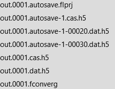
Inside Fluent Aero’s Project View, this out.000X.autosave.flprj file will be displayed as a hidden file inside the design point folder.
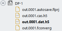
This feature is by default. When , additional settings are revealed to control when intermediate solutions are autosaved. These are described below.
Save Solution Every (Iterations)
Define the number of iterations between which an intermediate solution is saved. This option is shown if Autosave Intermediate Solution Files is .
Retain Only Most Recent Files
If , all intermediate solution files will be maintained on disk.
If , for all design points that are being updated, only the most recent intermediate solution files defined in Maximum Intermediate Solution Files will be maintained on disk.
If , for the last Design Point being updated, only the most recent intermediate solution files defined in Maximum Intermediate Solution Files will be maintained on disk.
Maximum Intermediate Solution Files
Define the number of most recent intermediate files that will be maintained on disk. This will appear if Retain Only Most Recent Files was enabled.
Post-Processing Output
Write Post Files
If this setting is , Fluent Aero will write post files (out.000#.cas.post,out.000#.dat.post) for each design point. These files can then be used to aid post-processing using Post-Analysis and/or EnSight. The files contain a subset of solution variables including some surface variables that are directly supported by Post-Analysis/EnSight. If these files have been printed, they can be viewed in Post-Analysis by right-clicking the DP folder in the Project View and selecting .
Zones
Select the zones you would like to save in the post-processing solution files (.post). This setting is only available if Write post-processing Files is enabled.
Post Variable List
Select the subset of variables that you would like to save in the post-processing solution files (.post). Three settings are available: , and .
: Velocity, Density, Temperature, Pressure, Heatflux and Shear Stress.
: Adds to the Mach Number, Viscosity, Thermal Conductivity, Cp, Wall Distance, Total Pressure, Total Temperature, Effective Viscosity and Pressure Coefficient.
: A fully configurable list of variables from Fluent’s available post-processing datasets.
This setting is only available if Write Post Files is enabled.
Additional Variables
Select any additional custom variables that you would like to save in the post-processing solution files (.post). This setting is only available if Write Post Files is enabled.
In this step, you instruct Fluent Aero to calculate the design points specified in the previous steps. Clicking Solve will reveal the Solve properties window.
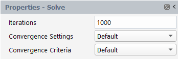
Iterations
This setting defines the maximum number of solver iterations that will be performed for each design point. If Convergence Settings is set to , the default number of iterations is 1000. If Convergence Settings is set to , the default number of iterations is 2000 when the conducting 3D simulations or 5000 for 2.5D simulations. If the calculation of a single design point reaches the maximum solver iterations or satisfies all convergence criteria, the calculation will stop, and the next design point will be automatically simulated.
This global setting instructs Fluent Aero on which type of default Solve settings to use. This global setting will affect all other Solve panel settings (those shown when is selected). , , , and can be selected.
Default
When is selected, Fluent Aero’s standard default solver settings will be used to update the design points. This should be used for the majority of Fluent Aero simulations.
When is selected, many other settings in the Solve panel (those shown when is selected) will be hidden by default, and their default values will be applied. The values used for each of these settings may change depending on the selected Domain Dimension, and Solver Type and the Flow Range associated with each design point. These settings have been tuned using the latest best practices of Fluent over a wide array of test cases with the goal of making the majority of simple external aero simulations converge successfully.
Below are a few major points that describe, in general, Fluent Aero’s default settings:
If the Solver Type is set to , the method will be used for the Solution Control.
If the Solver Type is set to , the method will be used for the Solution Control.
If the Solver Type is set to , and Domain Dimension is set to , the Length Scale Method will be set to and the Length Scale will be set to the specified in Geometric Properties. However, if the Domain Dimension is set to , the Length Scale Method will be set to . Refer to Pseudo Time Settings for the Calculation for more information.
When is used, more aggressive settings will be used for the lower Flow Range, such as , than for the higher Flow Range, such as . For more information, see Steering at the end of the current Inlets section under Boundary Zone Types Supported by Fluent Aero.
You can explore Fluent Aero’s default settings by first selecting the appropriate Domain Dimension and Solver Type and then using the function accessible by right-clicking on Solve in the Outline View (refer to Show Default Settings under Solve for more information).
When is selected, a more robust version of Fluent Aero’s solver settings will be used to update the design points. These settings may provide a more stable but slower convergence than the standard default solver settings. Therefore, it is recommended to increase the number of iterations to comply with the convergence criteria. This can be used for cases or design points that do not converge well using the default settings.
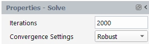
In the current release, is only available if Solver Type is set to and the Domain Dimension is set to .
When is selected, many other settings in the Solve panel (those shown when is selected) will be hidden by default, and their robust values will be applied. The values used for each of these settings may change depending on the selected Domain Dimension, and Solver Type and the Flow Range associated with each design point. These settings have been tuned using the latest best practices of Fluent over a wide array of test cases with the goal of making more difficult external aero simulations converge successfully.
Fluent Aero’s Convergence Settings follow the same general principles of the default settings, except that more relaxed values are used. For example, Courant Number and Time Scale Factor will be lower than, and iteration numbers will be longer than when Convergence Settings are used.
You can explore Fluent Aero’s settings by first selecting the appropriate Domain Dimension and Solver Type and then using the function accessible by right-clicking on Solve in the Outline View. Refer to Show Robust Settings under Solve for more information.
When is selected, none of Fluent Aero’s default solver settings will be applied or used to update the design points. In this situation, the user must ensure that a good set of solver settings has already been setup in the Fluent Solution workspace (such as Solution → Methods, Solution → Controls, etc.). Therefore, this setting should only be used by advanced users.
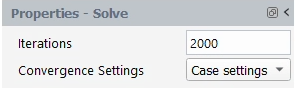
When is selected, additional options are revealed in the Solve panel. These additional settings represent other solver settings that can be useful to improve the convergence while updating the design points. These additional settings are described in detail in the following sections.
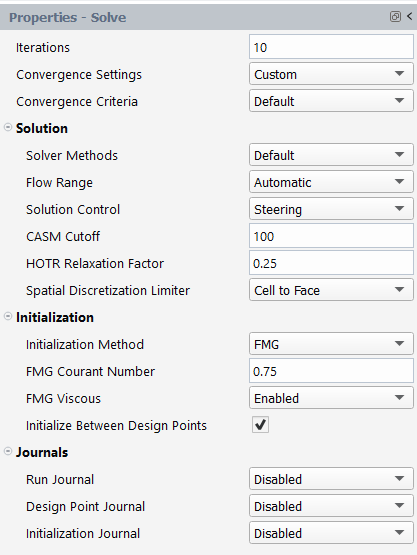
Solution
Solver Methods
This setting defines the solver settings used to perform the calculations.
When is selected, Fluent Aero will apply a subset of default solution methods to the background solver session. Some of these settings will change depending on if Solver Type is set to or , or on other features of the grid or simulation setup.
When Solver Type is set to , the following default Solution Methods will be applied:
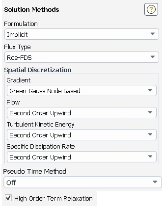
When Solver Type is set to , the following default methods will be applied:
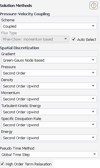
The following options may be enabled depending on various features of the mesh or simulation setup:
will be enabled when the density based solver type is used, except when the flow range is subsonic, then it will be disabled.
will always be enabled when the density-based solver is used. For the pressure-based solver, it will be enabled if the mesh contains any polyhedral or hexahedral cells. It will be disabled if it does not.
will be used in most cases, with the exception of design points that are simulated with a hypersonic flow range and a density based solver type, where will be used.
will be enabled for all cases, with cell quality based method disabled.
When is selected, Fluent Aero will not apply any settings to the solution methods of the background solver session. The solution methods already specified in the background solver session will be used. This option allows an advanced user to have full access to the list of solution methods available of the solver. To make changes to the solution methods to the background solver session, use the command, and in the window that appears, make the appropriate changes in the Methods panel.
Flow Range
This option only appears if Solver Type is set to .
This setting allows you to specify the expected flow range. By default, this is set to , which will use the design point conditions to set the flow range for each design point. In mode, the inlet Mach number will be used to select the flow range associated with each design point, using the following criteria:
0.0 < M <= 0.6 → Subsonic
0.6 < M <= 1.4 → Transonic
1.4 < M <= 2.5 → Low-Supersonic
2.5 < M <= 4.5 → High-Supersonic
4.5 < M → Hypersonic
However, you can manually set the flow range to either , , , , and if you know that their design points operate in a given flow regime. For instance, at high AoAs, a condition at Mach number 0.5 can produce a shock on the suction side of a wing. In this case, the Flow Range can be manually set to in order to improve convergence. Therefore, this option will help Fluent Aero tune various solver options for each type of simulation.
Solution Control
This setting is used to select the solver convergence strategy. The default option is Steering, but , and can also be selected. is not available if the Solver Type is set to . If is selected, the solver strategy setup in the initial case file, or from the Solution workspace window, will be used. Depending on the selection, a number of other settings may be revealed.
The following settings appear when Solution Control is set to :
Time Scale Factor: Controls the speed of convergence. Lower values result in a slower convergence speed but also potentially a better stability. The default value is 0.5. See Using the Solver for more information.
The following settings appear when Solution Control is set to :
Courant Number: Controls the speed of convergence. Lower values result in a slower convergence speed but also potentially a better stability. The default value is 5. See Using the Solver for more information.
The following settings appear when a specific Flow Range is selected and Solution Control is set to :
First to Higher Order Blending [%], Steering Stage 1 Iterations, Steering Stage 2 Update CFL After, Steering Stage 2 Update CFL Interval, Initial CFL, Maximum CFL, and Explicit Under-Relaxation Factor all control the speed and aggressiveness of convergence. The default values will change based on the selection made for the Flow Range. See Using the Solver for more information.
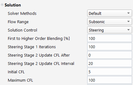
Note: When encountering more challenging simulations that lead to divergence, there are several settings that could be adjusted to try to achieve better convergence. First, inspect the quality of your initial solution. For instance, the use of initialization might require changes to its CFL and the number of multigrid levels and iterations to guarantee a smooth initial CFD solution before steering. If the quality of the initial solution is fine and if divergence occurs in stage 1, reduce the Initial CFL without going below 0.25 (suggestion) and increase the Steering Stage 1 Iterations without exceeding 250 (suggestion). If the above fails, then try to reduce the Explicit Under-Relaxation Factor without going below 0.4 (suggestion). If divergence occurs early in stage 2, reduce the Maximum CFL without going below 5 (suggestion) and/or increase the number of iterations of Steering Stage 2 Update CFL After or Steering Stage 2 Update CFL Interval without exceeding 200 and 40 respectively. If the above did not improve convergence, examine where divergence occurs in your computational domain. If divergence occurs near the surface, try to reduce the value of the CASM Cutoff without going below 25 (suggestion) and/or reduce the under-relaxation factors of the turbulence model. The latter can be accessed through the Fluent Solution workspace in Solution → Controls.
CASM Cutoff
This setting is used to select the cut-off multiplier for the (CASM) method. When a non-zero value is set, the enhanced CASM formulation will be applied whereas entering a value of 0 here will completely disable CASM. This option is only available when Solver Type is set to . Refer to Convergence Acceleration for Stretched Meshes (CASM) in the Fluent User's Guide for more information on this setting.
HOTR Relaxation Factor
This setting is used to select the Relaxation Factor for the method. Refer to High Order Term Relaxation (HOTR) in the Fluent User's Guide for more information on this setting. Entering a value of
0here will completely disable HOTR.Spatial Discretization Limiter
This setting is used to select the gradient limiter and is only available with the density-based solver. Refer to Selecting Gradient Limiters in the Fluent User's Guide for more information on this setting.
This is the default option. When selected, Fluent Aero will set the Limiter Type to and enable Cell to Face Limiting in the background solver session. The option is not directly enforced with this selection but is dependent on the activation of the high-speed numerics that is only available with the density-based solver.
When selected, Fluent Aero will set the Limiter Type to and enable Cell to Node Limiting and disable in the background solver session.
When is selected, Fluent Aero will not apply any settings to the gradient limiter of the background solver session.
Initialization
Initialization Method
This setting defines the method to initialize the simulation. Currently, , , , and are available. The default setting is .
initialization utilizes the Ansys Fluent FAS Multigrid technology to obtain the initial solution. Starting from a uniform solution (after performing standard initialization), the initialization procedure constructs the desired number of geometric grid levels, and then performs an initialization on each level starting from the coarsest grid level and ending with the finest grid level. More information on this method can be found in Overview of FMG Initialization.
Selecting initialization will reveal the FMG Courant Number and FMG Viscous settings in the Solve panel.
Many other initialization settings, including the Number of Multigrid Levels, and the Number of Cycles per Level, are specified automatically by Fluent Aero and will vary depending on if Convergence Settings is set to , or . In general, a higher number of cycles per level will be used for higher flow range, and in the mode.
After initializing a design point, you can view the settings that were automatically applied by going to the Solution workspace and viewing these settings in the appropriate text user interface option or graphical user interface panel. To modify these settings to be different than those automatically applied by Fluent Aero, first setting Initialization Method to , and then modify these values from the Solution workspace.
initialization will initialize the solution with a collection of recipes and boundary interpolation methods. It solves Laplace’s equation to determine the velocity and pressure fields. All other variables, such as temperature and turbulence, will be automatically patched based on domain averaged values or a particular interpolation recipe. By default, the number of iterations associated with the hybrid initialization will be set to 10 and the option will be enabled.
initialization will initialize the pressure, velocity, turbulence and temperature fields of the entire domain with constant initial values based on the Simulation Conditions used and applied to the or domain boundaries.
If is selected, the initialization method setup in the initial case file, or from the Solution workspace window, is used.
Note: Because of various limitations in the Fluent Solution workspace, in some specific situations, such as when the Solver Type is set to , or when the Solution Control is set to , an initialization will only occur if you manually trigger the initialization using a text user interface command. Therefore, in such cases, it may not be possible to get the FMG initialization to execute for all design points when using the option. A workaround is to use an Initialization Journal File.
FMG Courant Number
This setting can be used to set the Courant Number associated with the initialization. This setting is only visible if Initialization Method is set to .
FMG Viscous
This setting is used to enable the viscous mode of the FMG initialization. This setting is only visible if Initialization Method is set to FMG.
FMG Species
By default, the FMG initialization solves the transport species equations, but neglects volumetric reaction terms. This setting is used to enable species volumetric reactions during the FMG initialization. This setting is available only when density-based solver and a mixture Air Properties are selected in Airflow Physics and Initialization Method is set to .
Note: If the initial solution produced by does not improve as you reduce its Courant Number, conduct more iterations at each multigrid level. To increase these numbers, go to the Fluent Solution workspace and, in its Console (text user interface), type the following command:
solve->initialize->set-fmg-initializationand follow the steps described in Steps in Using FMG Initialization in the Fluent User's Guide. Next, to have Fluent Aero use these new settings, change Initialization Method to . In general, residuals below 1e-2 at end of level 1 (last multigrid level) will produce a suitable initial solution.Initialize Between Design Points
This setting is enabled by default. If enabled, when Update is selected, an initialization will be performed at the beginning of the calculation of each design point. If disabled, when Update is selected, only the first calculated design point will be initialized, however no initialization will be performed before any subsequent design point calculation. In this manner, subsequent design points will begin calculating starting from the final solution of the previously calculated design point and the iteration numbering will continue from the previous design points final iteration number.
Journals
This section allows you to setup Fluent journal (.jou) files that can be used to add extra control and setup to the Fluent solver at various points within the design point calculation process. These journal files will be read by the Fluent solver directly so they can only include settings that would affect the Fluent Solution workspace. The journal files cannot be used to change any settings that are located inside the Fluent Aero workspace. The default location to put these journal files is inside the Simulation folder (alongside the simulation case file).
Note: The journal files referred to by these options are scheme format .jou journal files that will be read and used by the Fluent solver to perform setup operations in the Fluent Solution workspace at various stages in the solution process. Fluent scheme commands or Fluent text user interface console commands can be used in these files. These are not the same as the python journal files that are read and used by Fluent Aero to perform setup operations in the Fluent Aero workspace.
There are three types of journal files, Run Journal, Design Point Journal and Initialization Journal, and each are applied at different steps in the settings application process.
Run Journal
This setting allows you to execute a journal file at the beginning of a run, after you press the command, and after all Fluent Aero’s default solver setup has been applied, but before design point specific settings and initialization settings are applied and before the initialization or calculation of any design point has been carried out. The default name to use for this journal file is run.jou. When enabled, the setting Run Journal File will appear, where you can enter the name and path to the journal file. The default name and path ./run.jou implies that there is a run journal file called run.jou located inside the simulation folder. All code inside this journal file should be in scheme format, and will be executed by the solver.
Design Point Journal
This setting allows you to execute a journal file before the initialization settings are applied and the initialization and calculation of each design point is carried out. The default name to use for this journal file is designpoint.jou. When enabled, the setting Design Point Journal File will appear, where you can enter the name and path to the journal file. The default name and path ./designpoint.jou implies that there is a design point journal file called designpoint.jou located inside the simulation folder. All code inside this journal file should be in scheme format, and will be executed by the solver.
Initialization Journal
This setting allows you to execute a journal file to replace the initialization routine that Fluent Aero would use for a design point. When this setting is , the Initialization Method setting will be set to Journal file. The default name to use for this journal file is initialization.jou. When enabled, the setting Initialization Journal File will appear, where you can enter the name and path to the journal file. The default name and path ./initialization.jou implies that there is a initialization journal file called initialization.jou located inside the simulation folder. All code inside this journal file should be in scheme format, and will be executed by the solver.
The figure below shows the order of operations Fluent Aero uses to apply settings after you click and before the calculation starts, including where the three journal file types are applied, if enabled.
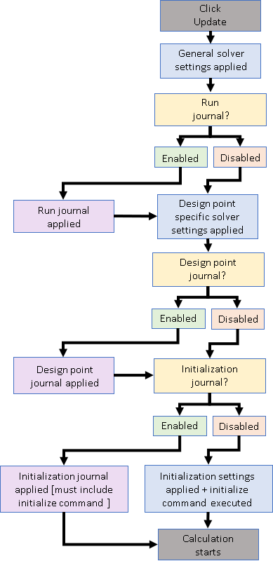
Convergence Criteria
This setting defines the convergence criteria of your simulation in Fluent Aero. The following options can be selected:
When is selected, Fluent Aero’s default convergence criteria will be used to check the convergence status of each design point. The following settings are only visible when is selected, but their default values will be set in the background solver session.
Residuals Convergence Cutoff
This setting defines the convergence residual value at which the calculation of a design point will stop if all the solver residuals drop below this value. By default, the convergence cutoff is set to 1e-5. The convergence condition is reached only when both Residuals Convergence Cutoff and Aero Coeff. Conv. Cutoff are satisfied.
Aero Coeff. Conv. Cutoff
This setting defines the convergence cutoff for the lift and drag coefficients. The default value is 2e-5 in most cases, except when the Solver Type is and the Domain Dimension is . In this case, the default is set 1e-4. The convergence condition is reached only when both Residuals Convergence Cutoff and Aero Coeff. Conv. Cutoff are satisfied.
Aero Coeff. Conv. Previous Values
This setting defines the number of iterations prior to the current iteration to be considered to estimate the convergence of lift and drag coefficients. The default value is 10. The coefficient of the current iteration will be compared with each of the last 10 values and the maximum difference will be used to compare with the cutoff setting.
Note: This maximum difference is normalized by the value of the current iteration.
When selected, the convergence criteria will be disabled. The solver will run until the number of iterations specified for each design point has been met.
When selected, the convergence settings described in the section above will become available and you can customize their values.

The following command buttons are available at the bottom of the Solve → Properties panel.

Note: The command button is available when Fluent Aero is waiting for you to start the calculation.
Once all the parameters and variables are set, Fluent Aero calculations can be started by clicking the button which is located on the bottom of the Solve panel, or by right-clicking Solve in the Outline View tree and selecting the command.
When the calculation starts, Fluent Aero will refer to the Input: Design Points table Status column to determine if and how a particular design point will be updated.
Design Points with Status set to will be updated starting from the beginning, including initialization.
Design Points with Status set to or will be updated starting from the previously written solution file (out.0*.dat[.h5]) associated with that design point.
Design Points with Status set to will only be initialized and no solver iterations will be updated.
Design Points with Status set to , , or will not be updated.
The following command button is available when Fluent Aero is calculating:

While the calculation is being performed, an button appears at the bottom of the Solve panel. If Interrupt is selected, the calculation will be interrupted at the next iteration.
Important: Interrupting a calculation does not save the results files (out.0*.dat[.h5] and out.0*.cas[.h5]) to the Design Point folder, and does not update the values in the results tables (Table:Summary, Table:Coefficients, Table:Residuals). If you would like to save your current solution to the results files and update the results tables, select .
After the calculation is complete or interrupted, additional commands will appear in the Solve panel.
The following command buttons are available after a calculation has been interrupted:

By clicking the button, Fluent Aero will continue the interrupted design point calculation from their previous state. The solution will not be initialized, and an additional set of iterations will be performed.
Before a is performed, any setting in the Solve panel can be adjusted, and these settings will be applied to the calculation. For example, you can change the Time Scale Factor allowing this new Time Scale Factor to be used for the remainder of the continued calculation.
However, while using the command, you cannot make any changes to the Geometric Properties, Simulation Conditions, Component Groups panel, or the Input Design Points table, as changes to these settings will set the Design Point Status to , and therefore will require a full update from a new initial solution.
When the calculation of a design point is interrupted, the data solution file is not saved and the tabulated results values are not computed or filled. If you want to save the results of the design point at the interrupted location, clicking will cause the data file to be saved and the tabulated results to be computed and filled.
This command will move on from the current design point that was interrupted, and cause the next design points in the sequence to be updated. The data solution file and the tabulated results of the current design point will not be saved, unless you select the command described above.
The following right-click commands are available by right-clicking the Solve step.
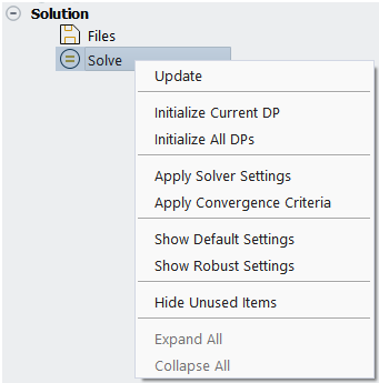
Note: Commands such as and , which are also available as command buttons, are instead described in Simulation Conditions.
This command will initialize the current design point only. If there has not yet been any design points updated, the first design point will be initialized. No iterations will be calculated. This allows you to verify if the initialization procedure is working well for a single design point before continuing with the calculation.
The current design point is typically the most recent design point that was updated or loaded, and will have its .dat[.h5] file shown in bold in the Project View. It is also possible to see the current design point by right-clicking the simulation folder, selecting Properties to view the simulation metadata, and finding the current key.
This command will initialize all design points. No iterations will be calculated. This allows you to verify if the initialization procedure is working well for all design points before continuing with the calculation.
In a typical workflow, when the command is used, Fluent Aero will first setup all settings in the solver and Solution workspace and then initialize and update the design points. If you would instead like to first verify what solver settings are setup inside the Solution workspace before continuing with the calculation, this command can be used. By selecting this command, Fluent Aero will immediately setup all solver settings inside the Solution workspace, allowing you to open the Solution workspace to verify the settings before calculating.
In a typical workflow, when the command is used, Fluent Aero will first create all convergence monitors and set up the convergence criteria in the solver and Solution workspace and then initialize and update the design points. If you would instead like to first verify what convergence monitors are setup inside the Solution workspace before continuing with the calculation, this command can be used. By selecting this command, Fluent Aero will immediately setup all convergence monitors and criteria inside the Solution workspace, allowing you to open the Solution workspace to verify the settings before calculating.
When Convergence Settings is set to , Fluent Aero will automatically apply default solver settings to use when calculating design points. These settings may change depending on the Solver Type, Domain Dimension and Flow Range used for each design point. However, this will all happen in the background, without necessarily showing the user which settings are being used.
If you would like to quickly view which settings are used when Convergence Settings is set to , you can use the command. Clicking this will open a window, where the Flow Range default settings can be selected.
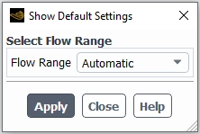
Clicking will set the Convergence Settings to (which will show all the underlying Solve settings), and set each setting to its default value based on the selected Flow Range. This option can be used to slightly modify the settings if convergence difficulties are experienced.
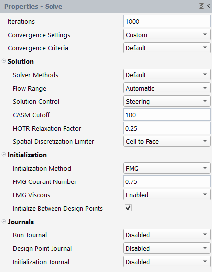
When Convergence Settings is set to , Fluent Aero will automatically apply robust solver settings to use when calculating design points. These settings may change depending on the Solver Type, Domain Dimension and Flow Range used for each design point. However, this will all happen in the background, without necessarily showing the user which settings are being used.
If you would like to quickly view which settings are used when Convergence Settings is set to , you can use the command. Clicking this will open a window, where the Flow Range default settings can be selected.
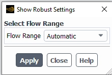
Clicking will set the Convergence Settings to (which will show all the underlying Solve settings), and set each setting to its default value based on the selected Flow Range. This option can be used to slightly modify the settings if convergence difficulties are experienced.
In the current release, is only available if Solver Type is set to and the Domain Dimension is set to .
After Results have been calculated, you may go back and modify settings inside Setup (Geometric Properties, Simulation Conditions, Component Groups), Solution (Solve) or in the Input: Design Point table. Depending on which settings are modified, the Results may no longer be up to date, and the status of the design points may change.
Modifying settings that define all design points will cause all design points to be set to .
Modifying any of the following settings will cause the Status of all design points to be set to .
Most settings in the Geometric Properties step will cause all design points to be set to , except for the following exceptions:
Domain Type cannot be changed after Results have been calculated.
Changing Reference Length and Reference Area trigger a special dialog, which is described in an upcoming section.
Changing any setting in the Airflow Physics will cause all design points to be set to , with one exception:
Adjusting the Transitional Regime Threshold when Knudsen Number Criterion is enabled will only affect the design points that transitioned into a different flow regime. For instance, if the threshold is decreased, some design points might shift into the rarefied flow regime, and only those will be set to Needs Update.
When Models-> Viscous is set to Reynolds Number Based, adjusting the Reynolds Number Threshold will only affect the design points that transitioned into a different flow regime. Modifying the Viscous Model will set only those design points that changed the viscous model to Needs Update.
Changing any input Parameter type in Simulation Conditions will cause all design points to be set to .
Changing the constant value of any parameter that is set to Distribution → in Simulation Conditions will cause all design points to be set to .
Changing the constant value of any input parameter defined on a specific zone in Component Groups will cause all design points to be set to .
Changing the name of any custom input parameter defined on a specific zone in Component Groups will cause all design points to be set to .
Changing the zone type or renaming any zone listed in Component Groups will cause all design points to be set to . This procedure will also trigger additional changes, such as a deletion of the run.settings file, as described in an upcoming section.
Modifying settings in the Input Design Point Table will cause an individual Design Point to be set to .
Changing an input value in the Input Design Point table that represents a single design point will cause the Status of that design point to be set to . If you would like to refresh the values of the design point table to match those that were calculated, you may use the command.
Modifying settings Solution → Solve will not change the status of a design point.
Modifying any settings in the Solve panel will not change the status of any design point. This is because you may want to calculate a design point simulation using a preliminary set of solver settings, then modify the settings and continue the calculation in order to follow a specific convergence method. You must take care of ensuring that the settings used to calculate each design point are as intended. To load the most recent Solve settings used to calculate an individual design point, you can right-click a design point folder in the Project View and select the command.
Modifying Reference Length and Reference Area
When neither the Reynolds Number Criterion nor Knudsen Number Criterion is active, the Reference Length and Reference Area has no impact on the CFD solution itself (.dat[.h5] file). However, they do affect the aerodynamic coefficients because these are non-dimensional forces. Therefore, if you modify the Reference Length or Reference Area after calculating any Results, follow the procedure, “Procedure to Update Results after Modifying Reference Length or Reference Area”, described below to only update these aerodynamic coefficients without recomputing a design point solution.
If either the Reynolds Number Criterion or Knudsen Number Criterion is active, modifying the Reference Length might change the flow regime for certain design points, therefore requiring recalculation of these design points. For design points within the same flow ranges, follow the procedure, “Procedure to Update Results after Modifying Reference Length or Reference Area”
Procedure to Update Results after Modifying Reference Length or Reference Area
If Reference Length or Reference Area is modified and at least one design point remains in the same flow regime, a panel will appear.
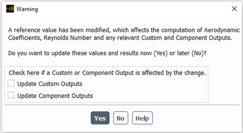
If you select , Fluent Aero will immediately update all Aerodynamic Coefficients and Reynolds numbers in all results tables or files of the design points that remain in the same flow regime. If any relevant custom or component output is affected, check Update Custom Outputs and/or Update Component Outputs, Fluent Aero will also load the solution file for these design points, and recompute the custom output value before updating the tables (this process may take some time).
If you select , Fluent Aero will not yet update the Aerodynamic Coefficients, and the Status of all design points that remain in the same flow regime will be set to Reference Values Modified. When you are ready to update these values, follow these steps:
Use the command button located in the Results tables properties panel.
From the panel that appears, check Update Custom Outputs and/or Update Component Outputs if any relevant custom or component output needs to be updated.
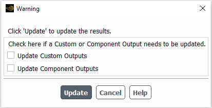
Click This will update the values of the aerodynamic coefficients, Reynolds number and relevant custom outputs and set the status of each design point back to . It is important to update the results before you close a simulation to ensure that the values are updated appropriately.
Modifying a Zone Type or Name
Generally, you should set up the full zone names and types before calculating any Results. If you modify the type or name of any zone listed in Component Groups after calculating Results, the following will occur:
The run.settings file, which contains the list of all zones, their names, types and their zone specific settings, will be deleted.
The Status of all design points will be set to . Furthermore, in this case, the status will also be saved to the design point folders, and therefore the Status cannot be refreshed by using the or command.
The following message will be printed to the console.
You must then re-save the run.settings to re-sync it with the case file by doing one of the following:
Selecting → , or
Clicking , or
Clicking when asked to save the case after closing the solver.
If you changed a zone type or name after calculating the results, it is important to re-save the run.settings file in one of the above recommended ways. Failing to do so could cause issues the next time you load your simulation.