


To create a simulation, a Fluent .cas[.h5] or a Fluent .msh[.h5] file must be loaded. This file has certain requirements to be compatible with a Fluent Aero simulation.
The Fluent .cas[.h5] or .msh[.h5] file must respect the following requirements:
3D Only
2D Fluent mode is not supported. 2D geometries are supported via 3D meshes with symmetry or periodic planes.
If you would like to simulate a type domain, a pressure-farfield boundary type or a pressure-farfield with pressure-outlet boundary type should be used to define the main farfield flow boundary. See more details in Freestream or WindTunnel Domain Type Requirements.
If you would like to simulate a type domain, a mass-flow-inlet or velocity-inlet boundary type should be used to define the inlet flow and a pressure-outlet boundary type should be used to define the outlet flow. See more details in Freestream or WindTunnel Domain Type Requirements.
Note: It is beneficial for the boundary zone names and types to be set up properly inside a Fluent Solution workspace or a Fluent Meshing workspace before importing the .cas[.h5] or .msh[.h5] file into Fluent Aero. Doing so will help Fluent Aero automatically set up the domain type as it imports the domain.
Note: Fluent Aero is intended for use in simulating external flow around aerodynamic objects, with:
Air as the fluid material
Steady-state flow
Viscous, Navier-Stokes flow
Stationary (non-dynamic) meshes
A flow domain modeling freestream flow, or flow inside a wind tunnel
Therefore, the features that are available in the Fluent Aero workspace are selected based on their applicability for such purposes. When calculating a solution, many of these features make use of the relevant feature in the connected (and normally hidden) Fluent Solution workspace. The Fluent Solution workspace, however, contains many more features that are intended for a broader range of applications. There may be some features that can be accessed in the Fluent Solution workspace that may not be relevant to the Fluent Aero workspace, so care should be taken when modifying settings from the Fluent Solution workspace. To learn more about how the Fluent Aero workspace is connected to the Fluent Solution workspace, go to Fluent Aero Workspace, the Solver Session, and the Fluent Solution Workspace.
Fluent Aero supports two domain types, and , each with a different set of requirements for the input mesh or case file. Furthermore, if the boundary zones are set up as recommended, Fluent Aero will be able to automatically determine the domain type and automatically set up the simulation and its associated or component group.
A domain type is used to simulate the airflow around an aircraft during typical in-flight conditions. The computational domain is setup such that its external boundaries are located far enough away from the aircraft model so that their presence does not impact the computational solution near the aircraft model. Typically, the distance between the aircraft model surface and the external boundaries is recommended to be at least 30 times the characteristic length of the aircraft.
Freestream Domain Type Requirements
Fluent Aero requires the following restrictions for the external boundary zones:
At least one pressure-far-field type boundary zone must be used to define the external freestream boundary of the domain.
A pressure-outlet type boundary zone may be used to define the general outlet flow region of the freestream domain. However, it must be attached to a pressure-far-field.
A symmetry type boundary zone may be used to represent a symmetric geometry.
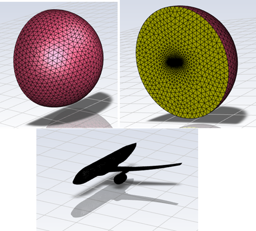
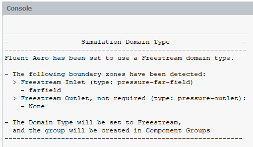
In the images below, a hemispherical pressure-far-field type boundary zone (red) with a circular symmetry type boundary zone surrounds the wall zones (grey) defining and aircraft geometry. In this case, no pressure-outlet type boundary zone is used to define the freestream domain.
Automatically Setup of a Freestream Group
Once Fluent Aero loads a mesh or case file, it will attempt to automatically determine if a domain type is being used.
First, it will search for a pressure-far-field type boundary zone that defines the freestream boundary of the domain. If one is found, Fluent Aero will determine that you are importing a type domain, and the pressure-far-field zone will be added to the Freestream group.
Next, it will search for a pressure-outlet boundary that is attached to the pressure-far-field, and if found, this boundary will also be added to the Freestream group.
A console message will appear to summarize the auto domain type setup. If there were any issues in setup, a warning will be printed, and you will have the opportunity to modify the Freestream group manually.
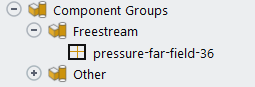
The Domain Type will be set to in the Geometric Properties step.
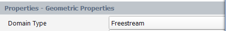
And, the pressure-far-field type zone and pressure-outlet type zones will be added to the Freestream group under Component Groups.
A domain type is used to simulate the airflow around an aircraft model inside an experimental wind tunnel test section. The computational domain is setup such that its external boundaries appropriately match those used for an experimental wind tunnel test, which may be located close enough to the aircraft model so that their presence has some impact on the computational solution near the aircraft model. The object of such a simulation would be to match as closely as possible the wall-effects associated with the wind tunnel test.
WindTunnel Domain Type Requirements
Fluent Aero requires the following restrictions for the external boundary zones:
A mass-flow-inlet or velocity-inlet type boundary zone must be used to define the wind tunnel inlet flow upstream of the aircraft model. It is recommended that this boundary be named windtunnel-inlet so that the automatic setup can register the boundary.
The inlet boundary zone should be normal to the direction of the flow, as the flow will be automatically set to be Normal to Boundary.
A pressure-outlet type boundary zone may be used to define the wind tunnel outlet flow downstream of the aircraft model. It is recommended that this boundary be named windtunnel-outlet so that the automatic setup can register this boundary.
wall, symmetry or periodic type boundary zones may be used to represent the wind tunnel walls. It is recommended that this boundary be named
windtunnel-wall*,windtunnel-symmetry*orwall-periodic*so that the automatic setup can register these boundaries.
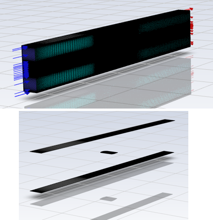
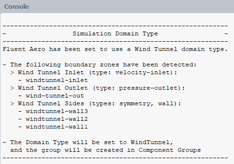
In the images below, a velocity-inlet type boundary zone (blue), a pressure-outlet type boundary zone (red), wall type (grey) and periodic type (teal) boundary zones define the wind tunnel domain while additional wall type (grey) boundary zones define an airfoil inside the test section.
Automatic Setup of a WindTunnel Group
Once Fluent Aero loads a mesh or case file, it will attempt to automatically determine if a domain type is being used.
First, it will search for any boundary that has windtunnel in its name (case insensitive and can include “ - “ in the name). If a boundary is found, Fluent Aero will determine that the Domain Type is being used.
Next, it will search for a velocity-inlet with windtunnel in its name, and add that boundary to the WindTunnel group.
Next, it will search for a pressure-outlet with windtunnel in its name, and add that boundary to the WindTunnel group
Finally, it will search for any wall or symmetry type boundaries with windtunnel in its name, and add those boundaries to the WindTunnel group.
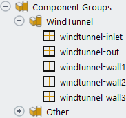
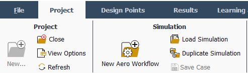
A console message will appear to summarize the auto domain type setup. If there were any issues in setup, a warning message will be printed, and you will have the opportunity to modify the WindTunnel group manually.
The Domain Type will be set to in the Geometric Properties step.

And, the windtunnel-* named zones will be added to the WindTunnel group under Component Groups.
If a new project has been created, the Fluent Aero application has no case loaded and presents an empty Project View window. A new Fluent Aero simulation can be created by clicking the button.
Select Simulation → to import a case file and create a new simulation. A window will appear where a case file (.cas, .cas.h5) or mesh file case file (.msh, .msh.h5) can be selected.
After a case file has been selected, a window will appear requesting a name for the new simulation. Clicking will create a new simulation in the currently open project folder. The case file will be copied into the new simulation folder and will be used as the primary case file for that simulation.
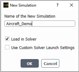
: If enabled, the solver is loaded with the selected case file. If disabled, the solver is not loaded, and you can choose to load the solver at a later time.
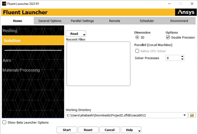
: If disabled, the solver will be loaded on your local machine and no further input will be required. However, if enabled, a Fluent Launcher window will appear. If so, set the appropriate number of Solver Processes, and, if necessary, specify the Remote machine or Scheduler and click .
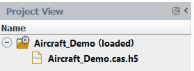
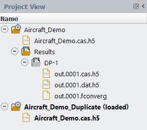
When the case import is complete, the new simulation folder appears in your Project View. This folder contains the case file that has been imported. If was selected, a solver session opens in the background, and the simulation folder is listed with (loaded) next to its name.
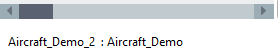
The currently selected simulation will be displayed in the bottom left corner of the Fluent Aero window, next to the currently opened project.
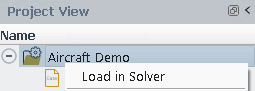
From the Project View, you can load a simulation by right-clicking a simulation folder and selecting , by double-clicking it, or by using Project → Simulations → .
By default, will launch a solver either on the same machine where Fluent Aero is open with your default number of CPUs, or on the requested machine using any other options provided in the initial Fluent Launcher (such as Use Job Scheduler, if any). Alternatively, if has been enabled in the Preferences, a Fluent Launcher window will appear allowing the specification of different options to launch the solver.
Once the simulation is loaded, (loaded) will appear next to the simulation folder name in your Project View, and the Fluent Aero Setup and Solution branches will be displayed in the Outline View.
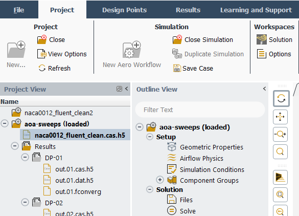
From the Project View, you can close a simulation by right-clicking a simulation folder and selecting .
From the Outline View, you can close a simulation by right-clicking a simulation folder and selecting . From the Project ribbon, you can close a simulation by clicking .
In both cases, the solver and the simulation will be closed and (loaded) will no longer appear next to the simulation.
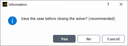
A panel may appear asking if you would like to save the case file before closing. Selecting is generally recommended, as it ensures that your simulation’s case file will be updated using any recent changes to the simulation.
You can duplicate a simulation by right-clicking a simulation folder in the Project View and selecting , or by selecting in the Project ribbon. A simulation may be duplicated if you would like to setup and calculate a new set of results starting from the same settings of your original simulation.
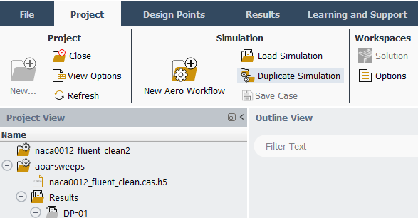
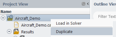
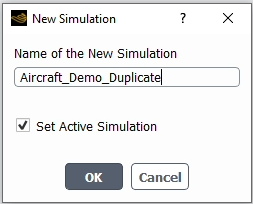
It is only possible to duplicate a simulation when no simulations are currently loaded. When is selected, a window will appear where you can enter the name for the new simulation. If is enabled, the newly duplicated simulation will be loaded after the duplication is performed.
A duplicated simulation will contain all the current settings of the original simulation folder, including all the settings applied in the Outline View (Geometric Properties, Simulation Conditions, Component Groups, Solve) and all the settings in the Input: Design Points folder. However, the Results folder will not be copied and none of the solution files will be copied.
The image below visually represents the interaction between the Fluent Aero workspace, the solver session and the Fluent Solution workspace.
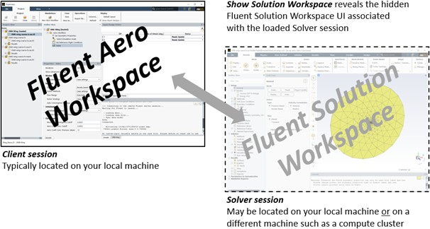
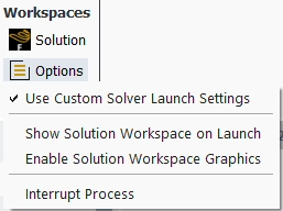
When you first open Fluent Aero, the user interface window that is presented is the Fluent Aero workspace. However, when you create or load a Simulation using or , a solver session will be loaded. By default, this solver session will be launched and your case file will be loaded in the background on your local machine – the same machine where your Fluent Aero workspace (or client session) is located. However, it is also possible to launch the solver on a different machine or with a different number of processes. In this way, it is possible for you to have the lightweight Fluent Aero workspace (where the majority of the user interaction takes place) located on a local machine with a more capable graphics display, but have the solver session (where the majority of the computational work takes place), located on the compute node of a cluster, which may have more CPU power and memory, but not have access to a graphics display. If you would like to launch the solver on a different machine, you may do so by enabling . This option can be found in Project → Workspaces → or from → → Aero.
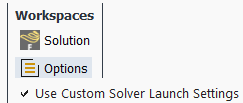
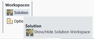
Furthermore, just like the Fluent Aero workspace represents the graphical user interface for the client session, the Fluent Solution workspace represents the graphical user interface for the solver session. Typically, the Fluent Solution workspace is hidden, because its interface is not required to setup and interact with Fluent Aero simulations. However, if you would like to interact with the Fluent Solution workspace, for example to setup more advanced settings that are not available from within the Fluent Aero workspace, you may do so by clicking Project → Workspaces → .
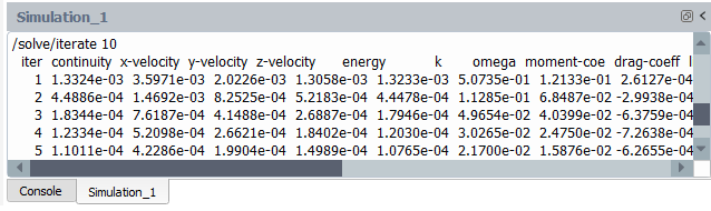
Note: By default, a single Console contains both the local Fluent Aero console transcript (displayed in black text), and the connected solver setting’s Fluent Solution workspace transcript (in gray text). All commands entered into the Fluent Aero console will be used locally in the Fluent Aero client. To send a text command to the solver session, right-click the simulation in the Outline View and choose
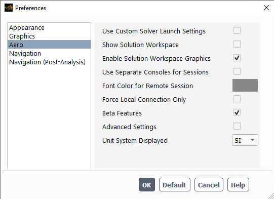
Preferences related to the solver session and the Solution workspace are available in Project → Workspaces and in → → Aero.
By default, when you create or load a Simulation using or , the Fluent Aero Simulation will load a solver session that is launched in the background on either:
The same machine and with the same number of processes you used to launch Fluent Aero.
On any machine using any other settings specified in the initial Fluent Launcher, such as Use Job Scheduler, if any.
However, it is also possible to use different settings to launch the solver on a different machine or with a different number of processes.
To do this, go to File → , select Aero, and enable .
If is enabled, the or command will first launch a Fluent Launcher window, where additional settings can be applied to determine how the solver is launched. This allows you to load the solver session on a different machine than where Fluent Aero is open, or to specify the Remote Machine or use a Job Scheduler (within ) to launch the solver on a cluster with a queuing system or with a different number of CPUs than what is specified as default.
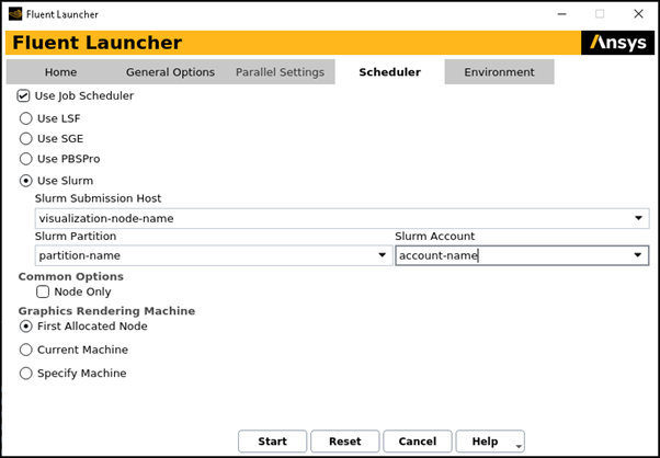
When using to , it is required to set the following settings in the Fluent Launcher that appears:
Mode → Solution
The solver session must be launched in Solution mode, as Fluent Aero is expecting to connect to a Solution workspace solver session in the background.
Dimension →
Options →
Note: When Fluent Aero is launched using the bin/aero (linux) or bin/aero.bat (windows) file, the Fluent Launcher will always appear when using or regardless of the setting specified in the Preferences panel.
(button) or
When this option is disabled, the Fluent Solution workspace associated with the solver session will be hidden. Enabling this option will cause a Solution workspace window to be shown, allowing the use of advanced settings that may not be available in the standalone Fluent Aero workspace.
When this option is disabled, the Fluent Solution workspace associated with the solver session will have its post-processing graphics window disabled. Enabling this option will cause a Solution workspace graphics window to be shown, allowing you to make post-processing graphical plots within the Solution workspace window.