


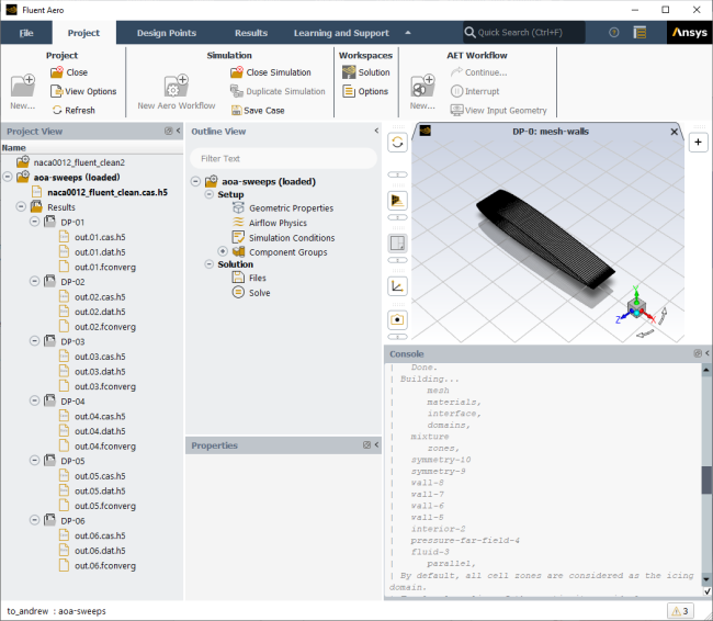
The Fluent Aero graphical user interface consists of the following components.
File (Top-Left)
Consists of file management commands (, , , etc.)
Ribbon (Top)
Project
Project management commands
Simulation management commands
Workspaces management commands
AET Workflow management commands
Design Points
Design point table management commands
Design point status management commands
Results
Select post-processing commands and quick-view actions
Project View (Left)
The left side panel shows the Project View by default. Before opening a project, this view shows available and recent projects that can be opened. Once a project is open, this view contains a list of all simulations, runs and output files contained in your Fluent Aero project.
Simulation Folders
The Project View will display a list of simulation folders, which are created when the option is used. If a solver session is currently loaded, (loaded) will be displayed next to the corresponding simulation folder name.
Results Folder
If a simulation has been calculated, a Results folder will appear inside the simulation folder. All output files of a particular run will be contained within the Results folder.
Outline View (Top-Center)
The Outline View is displayed in the top-center of the user interface, towards the upper right of the Project View by default. This view contains the currently loaded case. A loaded case is connected to a loaded solver session and provides access to:
Filter Text
Perform wild card and regular expression searches in the tree using the Filter Text entry box at the top of the tree where you can search and organize a list using a text string. For more details, see Filtering Lists and Using Wildcards in the Fluent User's Guide.
Setup
Contains steps to setup and organize your geometry and specify reference parameters and simulation conditions.
Geometric Properties
Settings to define the geometry orientation and reference sizes.
Airflow Physics
Settings to define various airflow physics models to use in your simulation, including solver type, turbulence model, and air properties.
Simulation Conditions
Settings to define the freestream flight conditions of each design point of your aerodynamic simulation (such as altitude, Mach number, etc.)
Component Groups
Settings to organize your mesh boundary zones into groups of aircraft components (such as , or components) and to define group or boundary zone specific conditions (such as engine exhaust temperature and mass flow).
Solution
Contains steps to setup your CFD solver parameters.
Solve
Settings to define and start the calculation process including default and robust proposed settings as well as custom and case settings solver and convergence parameters, if necessary.
Results
Access to quick post-processing features to explore the results of each design point.
Post-Analysis (Beta)
Access to detailed post-processing features to explore the results of each design point, including side by side comparison of solution files of different design points.
Properties Window (Bottom-Center)
Contains the settings of a selected item in the Outline View.
Graphics Window (Right)
Displays mesh, numerical, post-processed and monitoring data.
Console Window (Bottom-Right)
Displays the progress of your simulation and allows scripting of commands. The Fluent Aero console is a Python console.
By default, a single console contains both the local console and the Solution workspace transcript.
The Solution workspace transcript is prefixed by
|and displayed in gray. If multiple workspaces are connected simultaneously, the colors and the prefix will vary1|,2|, etc.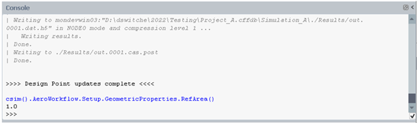
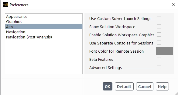
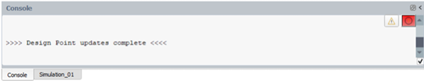
The Solution workspaces can be set to their own individual consoles by enabling under Preferences → Aero. The color of the Solution workspace transcript, when combined to the main console, can also be set in the preferences.
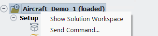
When entering a python command into the Console, it is applied directly to the Fluent Aero workspace. To send a text command to the Fluent Solution workspace and solver, right-click the simulation case in the Outline View and choose
Alternatively, you can go to the Solution workspace directly using the Workspaces → button in the Project ribbon to reveal the Solution workspace and enter the commands in that window directly.
Use the help menu (![]() ) icon in the upper right-hand corner of the workspace to access
its documentation. Some workspaces even have field-level user assistance that
provide information and guidance about a particular field.
) icon in the upper right-hand corner of the workspace to access
its documentation. Some workspaces even have field-level user assistance that
provide information and guidance about a particular field.
In addition to Online Technical Resources..., and the Product Improvement Program, you can also obtain information about the version and release of Fluent you are running by selecting the Version... option in help menu.
The top-right corner of the main window contains a layout menu. This menu permits to toggle between different panel distributions. Upon start-up, Fluent Aero will set up these panels using the view that was previously selected.
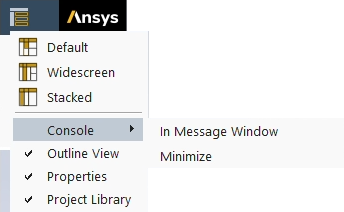
: The default view of the panels of Fluent Aero. Using this layout, the Project View will be displayed as a column on the left, and the Outline View will be displayed above the Properties panel as a single column to the right of the Project View.
: Using this layout, the Project View will be displayed as a column to the left, the Outline View will be displayed as a column to the right of the Project View, and the Properties panel will be displayed to the right of the Outline View.
: Using this layout, the Project View will be displayed as a column to the left, the Outline View will be displayed as a column to the right of the Project View, and the Outline View will be stacked in the same area behind the Project View. You can switch between displaying the Outline View and the Project View by selecting their associated tab. The Properties panel will be displayed to the right of the stacked Project View / Outline View.
: If enabled, the console is hidden, and accessible through the message window. To access the message window, click the message indicator at the bottom right of the main window.

The indicator icon changes if there are warning or error messages. If disabled, the console panel is displayed again.
: Show or minimize the console panel. When minimized, a panel is displayed in the left drawer.

The Fluent Aero menu consists of the following options.
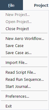
: Creates a new Fluent Aero project.
: Opens an existing project.
: Closes a project.
: Imports a Fluent case or mesh file, creates a new simulation, and loads a solver session.
: Saves the current settings to the Fluent case file stored in the simulation.
: Saves the current settings to a new case file. The new case file must be stored in the same simulation folder and will become the default case file of the simulation.
: Access the AET Workflow management commands.
: Copy a file external to the project, into the current simulation folder.
: Selects a python script file to execute.
: Selects a python script file to record and write a journal file of supported commands / stops writing.
: Opens the window. The Aero preference window is specific to Fluent Aero.
: Exits Fluent Aero. All solver sessions will also be terminated.
There are three ribbon commands: Project, Design Points and Results.
Project
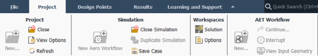
Project
: Creates a new Fluent Aero project.
: Opens an existing project. Command is available if no project is open.
: Closes a project. Command is available if a project is open.
: Provides options to change the display in the Project View.
: Refreshes the Fluent Aero user interface.
Simulations
: Imports a new case file and begins a new aero workflow simulation.
: Loads the simulation that has been selected in the Project panel. Command is available if no simulation is open.
: Closes the simulation that has been selected in the Project panel. Command is available if a simulation is open.
: Duplicates the simulation that has been selected in the Project panel.
: Saves the current settings to the Fluent case file stored in the simulation.
Workspaces
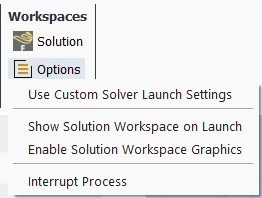
: Displays the Fluent Solution workspace solver window.
: Settings related to the Fluent solver workspace.
:
When enabled, or will first open a Fluent Launcher window, where additional settings can be applied to determine how the solver is launched. This allows you to load the solver on a different machine than where Fluent Aero is open, or to use a job scheduler to launch the solver on a cluster with a queuing system or with a different number of CPUs than what is specified as default. This option is also accessible in the Preferences panel.
:
The Fluent solver window will be shown as the solver is launched.
:
With this option enabled, the Fluent window will also have a graphics window.
:
This terminates the current Fluent solver and stops any process on the local or remote machine.
AET Workflow
:
Opens the New AET Workflow dialog.
:
Opens the Continue AET Workflow dialog.
:
Interrupts any currently running step of the AET workflow.
:
Loads the input 3D blade geometry into a separate SpaceClaim window where the geometry can be viewed and edited.
Design Points
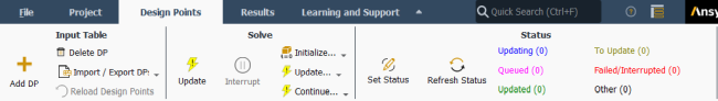
Input Table: Manages design point entries
: Add a new design point.
: Delete an existing design point.
: Import or export design points from or to a .csv file.
: Reload the design points table from Results. If Results have already been computed, this command will reload their respective design point table values, thereby removing any changes that may have been made since then.
Solve: Quickly launches a set of design points based on their status or predefined criteria.
: Update all design points that are set to , , or in the Input:Design Points table.
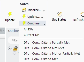
, and : Allows you to quickly initialize, update or continue a set of design points without manually setting their status in the Input:Design Points table. These options share the same drop-down menu as shown below.
: Initialize, update or continue to update all design points.
: Initialize, update or continue to update only the current design point.
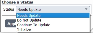
: Initialize, update or continue to update the design points that do not satisfy the convergence criteria that was set. See image below.
Status: Set or refresh the status of design points.
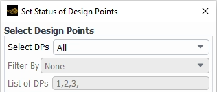
: Set the status of a group of design points. This command will open a panel where you can employ various filters to set the status of multiple design points simultaneously. This panel can be used to create a personalized set of design points to update, initialize or to save.
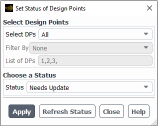
Select DPs: Controls which design point will be selected. Different types of selections are provided.
: Changes the status of all design points.
: Changes the status of a custom list of design points. To create this list, enter the design point numbers of interest in the List of DPs. Use commas (
,) and hyphens (-) to separate and create a group of design points within this list.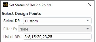
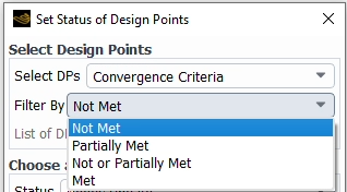
: Changes the status of the design points based on their convergence criteria. In Filter By, choose a convergence criterion. These criteria also appear in the Table:Summary of Fluent Aero under the Conv. Criteria Met? column.
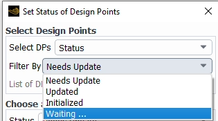
: Changes the status of the design points based on the Filter By status, as shown by the Status column in the Table:Summary.
Note: groups all the statuses that start with Waiting.
Choose a Status: Controls the new status that will be set to the design points selected. Press to set the new status of these design points.
: Refreshes the Status of each design point to the value that was obtained at the end of your most recent calculation or to , if no calculation has been performed or if simulation conditions have been modified after the calculation. This option is similar to the command in the Design Points → Status ribbon area.
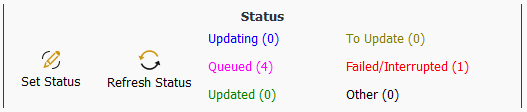
The second part of the Status section is a text area that shows the current number of design points that have a given status.
Updating (0) becomes Updating (DP-xx) during a calculation and shows the design point that is being updated. The corresponding status is Updating.
Queued (xx) shows the number of design points that are waiting to be updated. The status of these design points starts with in the Input:Design Points table.
Updated (xx) is the number of design points that have been updated or initialized. The corresponding status is either or .
To Update (xx) shows the number of design points that are to be updated. This represents design points with , , or statuses.
Failed/Interrupted (xx) shows the number of design points that diverged, failed or were interrupted. Therefore, this covers or statuses.
Other (xx) shows the number of design points that have other types of status.
Results

Dataset: Selects the currently active dataset, which will apply to the other Results ribbon options. The list contains any currently loaded Post-Analysis datasets, and one entry for any currently loaded Fluent simulation. A Post-Analysis dataset can be loaded from disk by using the command.
Quick-View: Accesses the post-processing shortcuts.
Surface, Graphics: Creates new post-processing objects for the Post-Analysis tool. These options are only available when the active dataset is set to a Post-Analysis dataset.
Plots: Create new line plots of post-processed data. can be used to generate an XY Plot of solution data from the active dataset. can be used to generate a graphical comparison of selected input and output variables across all design points in a simulation folder.
Dataset - Sequence: Select and sequence through the active datasets in the Post-Analysis tool.