


In Ansys Fluent, the modeling of flow in rotating and stationary components of turbomachines is possible with the use of a General Turbo Interface (GTI). The GTI provides a consistent workflow for connecting rotors to stators of different topology from full-wheel models to periodic-sectors to sectors with pitch-change of any pitch-ratio. A GTI can also be used to connect secondary flow paths such as cavities, injections, and bleeds to the main flow path of a turbomachine. GTIs are available in steady and transient simulations, and can be accessed for creation/editing by first selecting Turbo Models under Domain → Turbomachinery.
You can then click Turbo Create... from the following location:
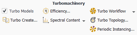
Turbomachinery ribbon under the Domain tab.
 Domain → Turbomachinery
→
Domain → Turbomachinery
→
Creating and editing a GTI is discussed in detail in Creating and Editing General Turbo Interfaces.
In most turbomachines, the number of blades in the rotor rows and the stator rows are not equal. Therefore, the adjacent rotor and stator blade row passages have a pitch-change. The most accurate simulations necessitate full-domain modeling or whenever pitchwise periodicity can be achieved (such as in periodic-sectors models). However, full-domain modeling is computationally demanding (in memory and CPU requirements). A pitch-change capable interface will alleviate these requirements by using one to a few blades per row to model the flow interaction between the rotor and stator blade passages. There are currently three types of pitch-change interfaces under GTI: Pitch-Scale (PS), No Pitch-Scale (NPS), and Mixing Plane (MP). These are discussed in Pitch-Change Models.
The PS and the NPS interface types provide two modeling techniques in handling pitch-change when using Frozen-Rotor (FR) model (a modeling strategy based on Multiple Moving Reference Frame) or Transient Rotor-Stator (TRS) model (a model based on Sliding Mesh Technique).
Note: In Fluent, the combination of GTI selection and Fluid zone motion specification you choose determines if the interface connecting the rotor to the stator is a Frozen-Rotor (FR), Transient Rotor-Stator (TRS), or Mixing-Plane (MP).
The basic rules are, GTIs straddling a fluid zone with zone motion specified as Mesh Motion are considered to be Transient Rotor-Stator interfaces, with pitch-change type PS or NPS specified during the GTI selection. On the other hand, GTI straddling a fluid zone with zone motion specified as Frame Motion can either be a Mixing-Plane interface or considered to be a Frozen-Rotor interface of the PS or the NPS pitch-change type.
The interface is implicitly defined as a Frozen Rotor or a Transient Rotor-Stator based on the Fluid zone motion specification. Therefore, you do not explicitly make interface selection called a Frozen-Rotor or a Transient Rotor-Stator.
There are three types of pitch-change interfaces:
Current compatibilities and limitations of the GTI and pitch-change options are:
Pitch-Scale and No Pitch-Scale options are available with the pressure-based coupled solver, density-based implicit solver, and SIMPLEC pressure based segregated solver (not available with other pressure-based segregated solvers or density-based explicit solver).
Mixing Plane option is available with the pressure-based coupled solver and density-based implicit solver only (not available with pressure-based segregated solvers or density-based explicit solver).
Available in relative velocity formulation in steady-state simulation with the pressure-based coupled solver
Available with all Species models.
Available with User-Defined Scalars.
Applies to 3D rotational turbomachines with rotor-stator configuration, such as axial or radial compressors and turbines, or torque converters.
Not available in 2D configuration or 3D translational problems (such as linear cascade).
Repartition is not supported for GTI.
Migration is not supported for GTI.
You can enable the Pitch-Scale interface from the Create/Edit Turbo Interfaces dialog box (Figure 14.5: Create/Edit Turbo Interfaces Dialog Box).
The Pitch-Scale interface maintains connectivity between blade passages by stretching or compressing the solution flux profiles on both sides of the interfaces. Pitch-scaling is valid for 3D rotational turbomachines, such as radial or axial turbines and compressors. It is also used for connecting a secondary flow-path to the main passage flow-path. The pitch-scale interface is available when the pitch-ratio between the connected passages is less than two. For connecting passages with pitch-ratio higher than two or full-wheel interfaces, the No Pitch-Scale interface should be used since it can handle any pitch-ratio.
Note: If you select the Pitch-Scale option for passages with pitch-ratio higher than two, Fluent will print a warning message informing you that you cannot use this pitch change option and will recommend that you use the No Pitch-Scale option. You can switch from Pitch-Scale to No Pitch-Scale after interface creation by editing the interface.
Note: In transient simulations, the Pitch-Scale option allows for transient interactions to take place between the connecting passages, but the exact frequency content of the interaction will not be preserved due to the periodic approximation made in this model. Therefore, this modeling strategy can be used to improve aerodynamic performance but not to predict accurate frequency content between the connected blade for a pitch-ratio not equal to one.
The Pitch-Scale option is available for use as a Frozen Rotor model if the fluid zone motion is set to Frame Motion or as a Transient Rotor-Stator model if the fluid zone motion is set to Mesh Motion.
You can enable the No Pitch-Scale interface from the Create/Edit Turbo Interfaces dialog box (Figure 14.5: Create/Edit Turbo Interfaces Dialog Box).
The No Pitch-Scale interface will maintain connectivity between blade row passages by creating virtual copies of the smaller passage flow profiles. The No Pitch-Scale interface is valid for 3D rotational turbomachines, such as radial or axial turbines and compressors. The No Pitch-Scale interface can be used for connecting a secondary flow-path to the main passage flow-path. The No Pitch-Scale interface is available for any pitch-ratio, including connecting a sector to a 360-degree interface or connecting full-wheel interfaces.
When the No Pitch-Scale interface is used between two zones with a large pitch difference, and if either Frame Motion or no motion is specified for the fluid zones, then total pressure loss across the interface can occur. To reduce the total pressure loss, an expert option is available via the following console command:
define/turbo-model/general-turbo-interface-settings/expert/nps-minimize-po-loss
Note: You can switch from Pitch-Scale to No Pitch-Scale after interface creation if the pitch-ratio of the connected passages is less than two.
Note: In transient simulations, the No Pitch-Scale option will allow for transient interactions to take place between the connecting passages, but the exact frequency content of the interaction will not be preserved due to the periodic approximation made in this model. Therefore, this modeling strategy can be used to improve aerodynamic performance due to the enhanced flow interaction captured over steady-state mixing-plane modeling but not to predict accurate frequency content between the connected blades for pitch-ratio not equal to one. The No Pitch-Scale interface can be used for asymmetric flow modeling or inlet distortion flow modeling.
Note: When the No Pitch-Scale interface is used to connect a sector to a 360-degree interface, the pitch of a sector should result in an integer number of passages in the 360-degree machine.
The No Pitch-Scale option is available for use as a Frozen Rotor model if the fluid zone motion is set to Frame Motion or as a Transient Rotor-Stator model if the fluid zone motion is set to Mesh Motion.
You can enable the Mixing-Plane interface from the Create/Edit Turbo Interfaces dialog box (Figure 14.5: Create/Edit Turbo Interfaces Dialog Box).
The mixing plane model in Fluent provides an alternative to the Frozen Rotor (multiple reference frame) and the Transient Rotor-Stator (sliding mesh models) models for simulating flow through domains with one or more regions in relative motion. In this implementation, a non-conformal interface capable of handling pitch-change topology is used to provide for the flow interaction between the blade rows. A pitchwise averaging procedure to mix out the flow variation between the blade rows is applied to the interfaces. The implicit nature of this implementation should provide a much more robust mixing process as well as fast convergence. This Mixing-Plane interface is an alternate and enhanced implementation of the profile-exchange base Mixing Plane model described in Legacy Mixing Plane Model.
As discussed in The Multiple Reference Frame Model, the MRF model and the Frozen Rotor model are applicable when the flow at the interface between adjacent moving/stationary zones is nearly uniform ("mixed out"). If the flow at this interface is not uniform, the Frozen Rotor model may not provide a physically meaningful solution. The Transient Rotor-Stator model (sliding mesh model, see Modeling Flows Using Sliding and Dynamic Meshes) may be appropriate for such cases, but in many situations it is not practical to employ a Transient Rotor-Stator model. For example, in a multistage turbomachine, if the number of blades is different for each blade row, a large number of blade passages is required in order to maintain circumferential periodicity. Moreover, sliding mesh calculations are necessarily unsteady, and therefore require significantly more computation to achieve a final, time-periodic solution. For situations where using the sliding mesh model is not feasible, the mixing plane model can be a cost-effective alternative.
In the mixing plane approach, each fluid zone is treated as a steady-state problem. Flow-field data from adjacent zones are passed as spatially averaged or "mixed" at the mixing plane interface. This mixing removes any unsteadiness that would arise due to circumferential variations in the passage-to-passage flow field (for example, wakes, shock waves, separated flow), therefore yielding a steady-state result. Despite the simplifications inherent in the mixing plane model, the resulting solutions can provide reasonable approximations of the time-averaged flow field.
The mixing plane model creates either radial or axial bands depending on the machine configuration (radial bands on axial machines and axial bands on radial machines). By default, a maximum of 40 equal width bands are requested for creating the interface bands between the upstream and downstream zone of the interface. The mixing plane model performs viability checks to remove bands with zero or very few faces in order to obtain proper pitchwise averaging. Therefore, while 40 bands are requested, the viability check may result in much fewer bands depending on the mesh density of the upstream and downstream zones of the mixing-plane interface.
After a mixing plane has been created, you can edit the model settings using the TUI
command:
/define/turbo-model/general-turbo-interfaces-settings/mixing-plane-model-settings
A List of General Turbo Interface text commands can be found under
define/
in the Fluent Text Command List.
Note: The Mixing Plane interface is available in transient simulations if the specified zone motion for the fluid zone straddling the mixing-plane is defined as Frame Motion. Fluent will not allow you to create a Mixing Plane interface on a fluid zone specified with Mesh Motion, and print a warning message.
If you have a case set up using the legacy profile-exchange based mixing-plane model and want instead to replace it with the current interface based mixing-plane model you must do the following:
In some modeling situations, you may need to model more than one blade per row and connect the blade ensemble via GTI in steady or transient simulations. There are restrictions on what can be modeled in Fluent using GTI (Pitch-Scale or No Pitch-Scale) and an ensemble of blades.
If the pitch-ratio of each ensemble (defined as 360 degrees divided by the pitch of ensemble) on both sides of the interface is an integer then both Pitch-Scale and No Pitch-Scale interfaces can be used in a Frame Motion or Mesh Motion simulation. However, if the pitch-ratio is a fraction on either side of the interface then only Frame Motion is allowed. In other words, transient-rotor-stator modeling of an ensemble can be performed only for ensembles with a pitch-ratio that is an integer.
For Mixing Plane interfaces, an ensemble can have a fraction or integer pitch-ratio because the Mixing Plane interface is available only with Frame Motion between the rotating and stationary zone.
Note: Frame Motion is available in both steady-state and transient simulation, while Mesh Motion is available only in transient simulation.
Figure 14.4: Ensemble Blade Rows with a GTI Interface shows multi-blade passage rows with a GTI between the rotor and IGV. The pitch-ratio of the rotor ensemble is a fraction while the pitch-ratio of the IGV ensemble is an integer (see Table 14.1: Pitch Ratio of Ensemble Blade Rows with GTI). In this example, you could only use the Pitch-Scale or No Pitch-Scale interface using Frame Motion, in either steady or transient simulation. This configuration is not suitable to model a transient-rotor-stator simulation where Mesh Motion must be specified for the rotor as the ensemble pitch-ratio is non-integer.
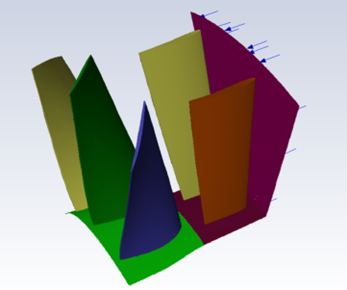
Table 14.1: Pitch Ratio of Ensemble Blade Rows with GTI
| Blade Row | # Blades in 360 deg. | # Blades in model | Pitch of ensemble deg. | Ensemble pitch-ratio (360/Pitch of ensemble) |
| IGV | 20 | 2 | 36 | 10 |
| Rotor | 16 | 3 | 67.5 | 5.333 |
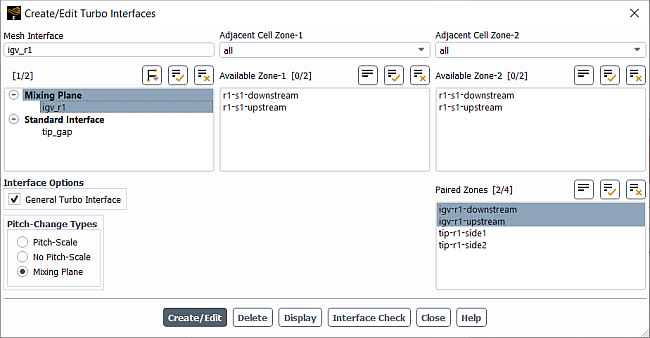
Most of the turbomachinery related interfaces required for blade row interaction can now be created from the Create/Edit Turbo Interfaces (Figure 14.5: Create/Edit Turbo Interfaces Dialog Box) panel. To access the Create/Edit Turbo Interfaces dialog box, you must first select Turbo Models from the ribbon under Domain → Turbomachinery.
Afterwards you can open the Create/Edit Turbo Interfaces dialog box from the ribbon:
![]() Domain → Turbomachinery
→
Domain → Turbomachinery
→
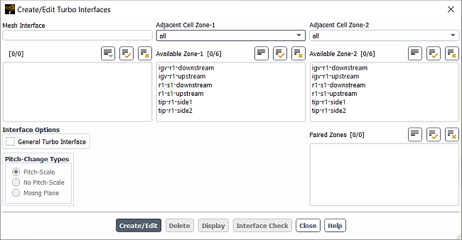
Enter a name for the interface in the Mesh Interface text-entry box.
Specify the interface zones that make up the mesh interface by selecting a zone in the Available Zone-1 list and the appropriate pair in the Available Zone-2 list.
You can filter the available zones using the Adjacent Cell Zone-1 and Adjacent Cell Zone-2 drop down lists. When you select a cell zone, the list of available interface zones are reduced to only those that are adjacent to that cell zone and currently not defined in another interface. Once the available zones are used in an interface, the zones will move to the Paired Zones list.
Enable the desired Interface Options:
You can create a non-turbo, non-periodic interface (for example, a tip gap interface) by leaving all Interface Options unselected.
Enable General Turbo Interface to connect two turbo zones.
The following Pitch-Change Types are available:
Pitch-Scale
No Pitch-Scale
Mixing Plane
See Pitch-Change Models for more information on these options.
Click to create a new mesh interface. The newly created interface appears in the list under Mesh Interface.
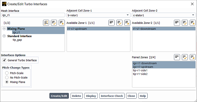
Highlighting an interface in the list will also highlight the appropriate interface zones in the Paired Zones list. You can use the
 button to group the
already created mesh interfaces by name or by type. Grouping by type as shown below can
be helpful to quickly identify a GTI interface.
button to group the
already created mesh interfaces by name or by type. Grouping by type as shown below can
be helpful to quickly identify a GTI interface.You can also multi-select already created Turbo Interfaces to edit, delete, display, and interface check multiple interfaces simultaneously. Note that you can only convert multi-selected turbo interfaces to a single Pitch-Change type.
Note: Whenever you delete and recreate a turbo interface during a solver run or if you are setting up a turbo interface for an initial run, you must initialize the solution before solving.
The buttons at the bottom of the dialog box allow you to take further actions, such as the following:
If you create an incorrect mesh interface, you can select it in the selection list and click the button to delete it. Any additional zones that were created when the interface was created will also be deleted.
You can click the button to display interface zones or mesh interfaces in the graphics window. Displaying is particularly useful if you want to check the location of the interface zones prior to setting up a mesh interface.
The button displays the following information about the selected interface(s) in the console:
Interface name
Interface options
Displays the Pitch-Change Type for the selected interface.
Blade-row-interaction configuration
Displays the interface configuration as sector-to-sector, 360-to-sector, or 360-to-360.
Interface zone pitch
Pitch ratio
Displays the ratio of larger pitch/smaller pitch.
Zone/side names
Zone/side area
Total intersection percentage
Typically, this number should be close to 100% to indicate full interface connectivity.
Periodic boundary touching zone/side check
This check informs whether a shared edge exists between the periodic boundaries and a zone/side forming the GTI interface for a blade row sector. A failure suggests you need to correct the geometry so that the periodic boundary touches the side/zone forming the GTI interface.
Ghost link check
This check examines whether an appropriate link exists between a ghost cell and its associated real cell. A failure means the Fluent solver may not run successfully.
Note: A ghost cell is the translated/rotated copy of a real cell in the domain. Fluent uses the ghost cell method to transfer flow variables between two different cell zones with the General Turbo Interface or in the phase-lag method for the same cell zone in the circumferential direction. A ghost link is the link between the ghost cell and its associated real cell.
Face ordering check
This check inspects whether the faces on ghost cells are created in the same order as on the real cells.
An example of an Interface Check is shown below:
-------------------------------------------------------------------------------------------------
 Interface Name:     igv-r1-ps
 Interface Options:  Turbo - Pitch-Scale - Blade row interaction
 Blade-row-interaction configuration : sector-to-sector
 Interface zone1 pitch(deg) : 13.846154, Interface zone2 pitch(deg) : 15.652174
 Pitch ratio :   1.1304
-------------------------------------------------------------------------------------------------
                         Side-1 name (id): igv-r1-upstream (12)
                              Side-1 area: 2.79350456e-03
                         Side-2 name (id): igv-r1-downstream (28)
                              Side-2 area: 3.15787308e-03
                 Side1 intersection total:  99.9996%
                 Side2 intersection total:  99.9993%
 Checking ghost cell for a sliding interface: igv-r1-ps
 for thread 12, adj. thread0 14, adj. thread1 16
 for thread 28, adj. thread0 30, adj. thread1 31
Periodic boundary touching igv-r1-upstream check...successful.
Periodic boundary touching igv-r1-downstream check...successful.
Ghost link check...successful.
Face ordering check...successful.
This mixing-plane model is based on profile boundary exchange. It can be accessed from the TUI command:
/define/turbo-model/legacy-models/legacy-mixing-plane>
It is advised that you utilize the updated mixing plane model from the General Turbo Interface described in Blade Row Interaction Modeling.
Note: The legacy mixing plane model is only available if you have deselected Enable under Turbo Model.
Note the following limitations of the mixing plane model:
The LES turbulence model cannot be used with the mixing plane model.
The models for species transport and combustion cannot be used with the mixing plane model.
The VOF multiphase model cannot be used with the mixing plane model.
The discrete phase model cannot be used with the mixing plane model for coupled flows. Non-coupled computations can be done, but you should note that the particles leave the domain of the mixing plane.
You can find more information about the following topics in the Theory Guide:
The model inputs for mixing planes are presented in this section. Only those steps relevant specifically to the setup of a mixing plane problem are listed here. Note that the use of wall and periodic boundaries in a mixing plane model is consistent with their use when the model is not active.
Select the Absolute or Relative Velocity Formulation in the General Task Page, when the pressure-based solver is enabled.
 Setup →
  General
Important: When the density-based solver is enabled, only the Absolute Velocity Formulation can be used with the mixing plane model.
For each cell zone in the domain, specify its angular velocity (
 ) and the axis about which it rotates. Setup → Cell Zone
Conditions
) and the axis about which it rotates. Setup → Cell Zone
Conditions
If the zone is rotating, or if you plan to specify cylindrical-velocity or flow-direction components at inlets to the zone, you must define the axis of rotation for the frame of reference. In the Fluid dialog box or Solid Dialog Box, specify the Rotation-Axis Origin and Rotation-Axis Direction under the Reference Frame tab.
In the Fluid (Figure 10.4: The Fluid Dialog Box Displaying Frame Motion Inputs) or Solid dialog box, enable the Frame Motion option and then set the Speed under Rotational Velocity and/or the X, Y, and Z components of the Translational Velocity in the expanded portion of the dialog box under the Reference Frame tab.
Important: It is important to define the axis of rotation for the cell zones on both sides of the mixing plane interface, including the stationary zone.
Define the velocity boundary conditions at walls, as described in step 3 of Setting Up Multiple Reference Frames.
Define the boundary conditions at the inlets, as described in Boundary Conditions. For velocity inlets, you can choose to define either absolute velocities or velocities relative to the motion of the adjacent cell zone (specified in step 2). For pressure inlets and mass-flow inlets, the specification of the flow direction and total pressure will always be absolute, because the absolute velocity formulation is always used for mixing plane calculations. For a mass-flow inlet, you do not need to specify the mass flow rate or mass flux. Ansys Fluent will automatically select the Mass Flux with Average Mass Flux specification method and set the correct values when you create the mixing plane, as described in More About Mass Flux and Average Mass Flux.
Details about these inputs are presented in Defining the Flow Direction, Defining the Velocity, and Inputs at Mass-Flow Inlet Boundaries.
Important: Note that the outlet boundary zone at the mixing plane interface must be defined as a pressure outlet, and the inlet boundary zone at the mixing plane interface must be defined as either a velocity inlet (incompressible flow only), a pressure inlet, or a mass-flow inlet. The overall inlet and exit boundary conditions can be any suitable combination permitted by the solver (for example, velocity inlet, pressure inlet, or mass-flow inlet; pressure outlet). Remember, however, that if mass conservation across the mixing plane is important, you must use a mass-flow inlet as the downstream boundary; strict mass conservation is not maintained across the mixing plane when you use a velocity inlet or pressure inlet.
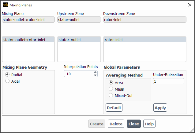
Define the mixing planes in the Mixing Planes Dialog Box (Figure 14.8: The Mixing Planes Dialog Box) accessed only from the TUI:
/define/turbo-model/legacy-models/legacy-mixing-plane/mixing-plane-guiSpecify the two zones that make up the mixing plane by selecting an upstream zone in the Upstream Zone list and a downstream zone in the Downstream Zone list. It is essential that the correct pairs be chosen from these lists (that is, that the boundary zones selected lie on the mixing plane interface). You can check this by displaying the mesh.
Setup →
General → Display...
(3D only) Indicate the geometry of the mixing plane interface by choosing one of the options under Mixing Plane Geometry.
A Radial geometry signifies that information at the mixing plane interface is to be circumferentially averaged into profiles that vary in the radial direction, for example,
 ,
,  . This is the case for axial-flow machines, for example.
An Axial geometry signifies that circumferentially averaged profiles are to be constructed that vary in the axial direction, for example,
 ,
,  . This is the situation for a radial-flow device.
Important: Note that the radial direction is normal to the rotation axis for the fluid zone and the axial direction is parallel to the rotation axis.
(3D only) Set the number of Interpolation Points. This is the number of radial or axial locations used in constructing the boundary profiles for circumferential averaging. You should choose a number that approximately corresponds to the resolution of the surface mesh in the radial or axial direction. Note that while you can use more points if you want, the resolution of the boundary profile will only be as fine as the resolution of the surface mesh itself.
In 2D the flow data is averaged over the entire interface to create a profile consisting of a single data point. For this reason you do not need to set the number of Interpolation Points or select a Mixing Plane Geometry in 2D.
Set the Global Parameters for the mixing plane.
Select the Averaging Method. The Area averaging method is the default method. For detailed information about each of the Area, Mass, or Mixed-Out options, see Choosing an Averaging Method in the Theory Guide.
Set the Under-Relaxation parameter. It is sometimes desirable to under-relax the changes in boundary values at mixing planes as these may change very rapidly during the early iterations of the solution and cause the calculation to diverge. The changes can be relaxed by specifying an under-relaxation less than 1. The new boundary profile values are then computed using

(14–1)
where
 is the under-relaxation factor. Once the flow field is
established, the value of
is the under-relaxation factor. Once the flow field is
established, the value of  can be increased.
Click to set the Global Parameters. If the button is visible to the right of the button, clicking the button will return Global Parameters back to their default values. The button will then change to be a button. Clicking the button will change the Global Parameters back to the values that were last applied.
Click to create a new mixing plane. Ansys Fluent will name the mixing plane by combining the names of the zones selected as the Upstream Zone and Downstream Zone and enter the new mixing plane in the Mixing Plane list.
If you create an incorrect mixing plane, you can select it in the Mixing Plane list and click the button to delete it.
There are two options available for use with the mixing plane model: a fixed pressure level for incompressible flows, and the swirl conservation described in Swirl Conservation in the Theory Guide.
For certain turbomachinery configurations, such as a torque converter, there is no fixed-pressure boundary when the mixing plane model is used. The mixing plane model is usually used to model the three interfaces that connect the components of the torque converter. In this configuration, the pressure is no longer fixed. As a result, the pressure may float unbounded, making it difficult to obtain a converged solution.
To resolve this problem, Ansys Fluent offers an option for fixing the pressure level. When this option is enabled, Ansys Fluent will adjust the gauge pressure field after each iteration by subtracting from it the pressure value in the cell closest to the Reference Pressure Location in the Operating Conditions Dialog Box.
Important: This option is available only for incompressible flows calculated using the pressure-based solver.
To enable the fixed pressure option, use the
fix-pressure-level text command:
/define/turbo-model/legacy-models/legacy-mixing-plane/set/fix-pressure-level
Conservation of swirl is important for applications such as torque converters
(Swirl Conservation in the Theory Guide). If you want to enable
swirl conservation across the mixing plane, you can use the commands in the
conserve-swirl text menu:
/define/turbo-model/legacy-models/legacy-mixing-plane/set/conserve-swirl
To turn on swirl conservation, use the enable? text
command. Once the option is turned on, you can ask the solver to report information
about the swirl conservation during the calculation. If you turn on
verbosity?, Ansys Fluent will report for every iteration
the zone ID for the zone on which the swirl conservation is active, the upstream and
downstream swirl integration per zone area, and the ratio of upstream to downstream
swirl integration before and after the correction.
To obtain a report of the swirl integration at every pressure inlet, pressure
outlet, velocity inlet, and mass-flow inlet in the domain, use the
report-swirl-integration command. You can use this
information to determine the torque acting on each component of the turbomachinery
according to Equation 2–22 (in
the Theory Guide).
One of the options available in the mixing plane model is to conserve total enthalpy across the mixing plane. This is a desirable feature because global parameters such as efficiency are directly related to the change in total enthalpy across a blade row or stage.
The procedure for ensuring conservation of total enthalpy simply involves adjusting the downstream total temperature profile such that the integrated total enthalpy matches the upstream integrated total enthalpy.
If you want to enable total enthalpy conservation, you can use the commands in the
conserve-total-enthalpy text menu:
/define/turbo-model/legacy-models/legacy-mixing-plane/set/conserve-total-enthalpy
To turn on total enthalpy conservation, use the enable?
text command. Once the option is turned on, you can ask the solver to report
information about the total enthalpy conservation during the calculation. If you turn
on verbosity?, Ansys Fluent will report at every iteration
the zone ID for the zone on which the total enthalpy conservation is active, the
upstream and downstream heat flux, and the ratio of upstream to downstream heat
flux.
It should be emphasized that the mixing plane model is a reasonable approximation so long as there is no significant reverse flow in the vicinity of the mixing plane. If significant reverse flow occurs, the mixing plane will not be a satisfactory model of the actual flow. In a numerical simulation, reverse flow often occurs during the early stages of the computation even though the flow at convergence is not reversed. Therefore, it is helpful in these situations to first obtain a provisional solution using fixed conditions at the rotor-stator interface. The mixing plane model can then be enabled and the solution run to convergence.
If you are using the mass or mixed-out averaging method and you are experiencing convergence problems in the presence of severe reverse flow, initialize your solution using the default area-averaging method, then switch to mass or mixed-out averaging after the reverse flow dies out.
Under-relaxing the changes in the mixing plane boundary values can also help in
troublesome situations. In many cases, setting the under-relaxation factor to a value less
than 1 can be helpful. Once the flow field is established, you
can gradually increase the under-relaxation factor.