


To reduce blade row simulation cost in turbomachinery you can model blade row coupling (rotor / stator interaction) using a technique known as frozen gust or inlet disturbance flow modeling. In this modeling strategy, the wake of the upstream row is obtained usually from a steady-state simulation and imposed as an inlet profile on the downstream blade row. The same can be done with the potential field from the downstream row on an upstream row. By doing this, the blade row interaction problem is reduced to a single row with imposed inlet and/or outlet profiles.
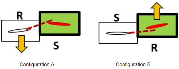
There are two possible variations of this flow problem. See Figure 14.3: Frozen Gust variations.
Wake from a rotor imposed on stator row (configuration A).
Wake from a stator imposed on rotor row (configuration B).
The common workflow for the frozen gust / inlet disturbance modeling approach is as follows:
Perform a steady-state simulation of the blade row interactions for the rotor / stator configuration of interest using either the mixing plane or frozen-rotor method. See The Multiple Reference Frame Model or Legacy Mixing Plane Model.
Extract the wake profile from the neighboring row (wake of the upstream row or potential field of the downstream row). See Reading and Writing Profile Files.
Expand the wake profile to full wheel using the Replicate Profile dialog box. See Replicating Profiles.
Apply the expanded profile to the boundary of interest, typically an inlet, on the rotor or stator depending on the configuration.
The final step is dependent on which configuration you are modeling.
For rotor wake imposed on stator passage (configuration A):
The profile must be linked to a reference frame that is rotating with the rotor. See Using Profiles.
For stator wake imposed on a rotor passage (configuration B):
The motion of the rotor with respect to the stationary stator wake profile can be modeled using the standard Mesh Motion feature in Fluent, where the rotation of the rotor and the axis of rotation are specified in the fluid cell zone conditions. See Defining Zone Motion.