


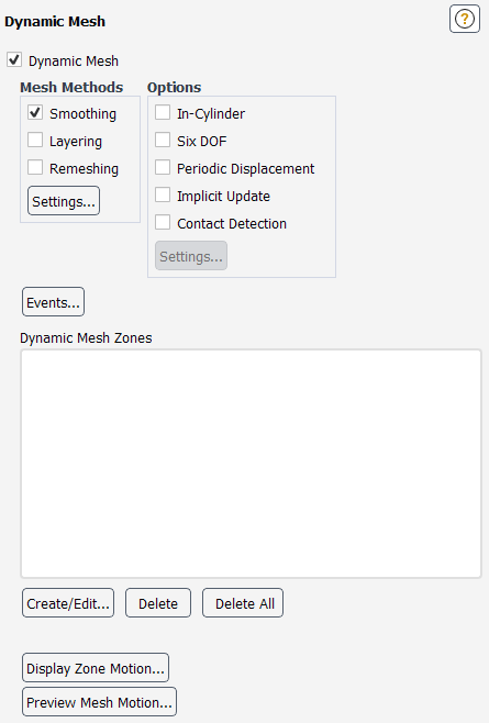
The Dynamic Mesh task page allows you to define the all the parameters for modeling a dynamic mesh model. See Setting Dynamic Mesh Modeling Parameters for details about using the items below.
Controls
- Dynamic Mesh
enables the dynamic mesh model and activates the controls in the task page.
- Mesh Methods
contains options to specify the mesh update method(s).
- Smoothing
enables mesh smoothing. See Smoothing Methods for details about the smoothing methods available.
- Layering
enables the dynamic layering method that can be used to add or remove layers of cells adjacent to a moving boundary based on the height of the layer adjacent to the moving surface in prismatic mesh zones. See Dynamic Layering for details.
- Remeshing
enables remeshing methods. For details, see Remeshing.
- Settings...
displays the Mesh Method Settings Dialog Box in which you can specify settings for the Smoothing, Layering, and Remeshing methods.
- Options
contains options to specify specialized dynamic mesh models.
- In-Cylinder
enables the in-cylinder model. See In-Cylinder Settings for more information.
- Six DOF
enables the six degrees of freedom (DOF) solver. See Six DOF Solver Settings for more information.
- Periodic Displacement
enables periodic displacement for blade flutter analysis. See Using Dynamic Mesh Zones in a Blade Flutter Simulation for more information.
- Implicit Update
specifies that the mesh is updated during a time step (as opposed to just at the beginning of a time step). See Implicit Update Settings for more information.
- Contact Detection
enables contact detection. See Contact Detection Settings for more information.
- Settings...
opens the Options Dialog Box, where you can set the parameters for the options that are enabled in the Options group box.
- Events...
displays the Dynamic Mesh Events Dialog Box.
- Dynamic Mesh Zones
displays a list of dynamic mesh zones.
- Create/Edit...
displays the Dynamic Mesh Zones Dialog Box.
- Delete
removes the selected dynamic zone(s) from the Dynamic Mesh Zones list.
- Delete All
removes all dynamic zones from the Dynamic Mesh Zones list.
- Display Zone Motion...
displays the Zone Motion Dialog Box.
- Preview Mesh Motion...
displays the Mesh Motion Dialog Box.
For additional information, see the following sections:
- 51.9.1. Mesh Method Settings Dialog Box
- 51.9.2. Mesh Smoothing Parameters Dialog Box
- 51.9.3. Advanced Remeshing Settings Dialog Box
- 51.9.4. Mesh Scale Info Dialog Box
- 51.9.5. Options Dialog Box
- 51.9.6. In-Cylinder Output Controls Dialog Box
- 51.9.7. Six DOF Properties Dialog Box
- 51.9.8. Periodic Displacement Group Dialog Box
- 51.9.9. Periodic Displacement Properties Dialog Box
- 51.9.10. Flow Control Settings Dialog Box
- 51.9.11. Dynamic Mesh Events Dialog Box
- 51.9.12. Define Event Dialog Box
- 51.9.13. Events Preview Dialog Box
- 51.9.14. Dynamic Mesh Zones Dialog Box
- 51.9.15. Orientation Calculator Dialog Box
- 51.9.16. Zone Scale Info Dialog Box
- 51.9.17. Zone Motion Dialog Box
- 51.9.18. Mesh Motion Dialog Box
- 51.9.19. Autosave Case During Mesh Motion Preview Dialog Box
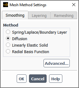
The Mesh Method Settings dialog box allows you to apply settings for the smoothing, layering, or remeshing methods.
Controls
- Smoothing
contains parameters to be specified for the smoothing mesh update method.
- Method
allows you to specify the smoothing method.
- Spring/Laplace/Boundary Layer
specifies that the smoothing method is spring based, or appropriate for the Laplacian smoothing method (for 2.5D remeshing) or the boundary layer smoothing method.
- Diffusion
selects the diffusion-based smoothing method.
- Linearly Elastic Solid
selects smoothing based on the equations for a linearly elastic solid.
- Radial Basis Function
selects smoothing that is based on a radial basis function interpolation, so that Fluent solves for a displacement field that satisfies the displacements at boundaries with prescribed motion and then interpolates the displacements onto all other nodes in the interior and at the deforming boundaries.
- Advanced...
opens the Mesh Smoothing Parameters Dialog Box, in which you can define the settings for the selected smoothing Method.
- Layering
contains parameters to be specified for the layering mesh update method.
- Options
specifies the criteria for splitting or collapsing cell layers.
- Height Based
specifies that the cell layers are split or merged based on height.
- Ratio Based
specifies that the cell layers are split or merged based on ratios.
- Split Factor
specifies the value of
 in Equation 13–15. It controls the height
or ratio at which the cells are split.
in Equation 13–15. It controls the height
or ratio at which the cells are split.- Collapse Factor
specifies the value of
 in Equation 13–16. It controls the
height or ratio at which the cells are collapsed and merged into the
next layer.
in Equation 13–16. It controls the
height or ratio at which the cells are collapsed and merged into the
next layer.
- Remeshing
contains parameters to be specified for the remeshing mesh update method. For details about using the controls that follow, see Remeshing.
- Methods-Based Remeshing
allows you to selectively enable a variety of remeshing options, each of which is suitable for particular kinds of cell types.
- Unified Remeshing
specifies that an algorithm is applied that combines aspects of a variety of remeshing methods and by default attempts to maintain the initial mesh size distribution even as the mesh moves. It is applied to triangular or tetrahedral cells and can produce wedge cells in 3D boundary layer meshes. It simplifies the setup and can provide increased robustness, especially for parallel simulations.
- Advanced...
opens the Advanced Remeshing Settings Dialog Box, in which you can revise the default settings for the Unified Remeshing method.
- Methods
contains options that control remeshing. This group box is only available if you have selected Methods-Based Remeshing.
- Local Cell
allows you to remesh deforming boundary cells.
- Local Face
allows you to remesh deforming boundary faces. This option is available for 3D cases.
- Region Face
allows you to remesh a region.
- 2.5D
enables the 2.5D model. This option is only available for 3D cases. See Using the 2.5D Model for more information.
- Parameters
contains parameters that control remeshing. This group box is only available if you have selected Methods-Based Remeshing.
- Minimum Length Scale
specifies the lower limit of cell size below which the cells are marked for remeshing.
- Maximum Length Scale
specifies the upper limit of cell size above which the cells are marked for remeshing.
- Maximum Cell Skewness
specifies the desired maximum skewness for the mesh.
- Maximum Face Skewness
specifies the desired maximum skewness for the surface mesh. If you selected Methods-Based Remeshing, this option is only available when Local Face is enabled under Methods.
- Size Remeshing Interval
specifies the interval in time steps for remeshing based on the above size criteria only. Marking of cells based on skewness occurs automatically at every time step when Remeshing is enabled. This field is only available if you have selected Methods-Based Remeshing.
- Mesh Scale Info...
opens the Mesh Scale Info Dialog Box, in which you can view the statistics of the mesh, such as the minimum and maximum length scale values and the maximum cell and face skewness values.
- Default
sets the fields in the group box to values that represent a reasonable starting point for your particular mesh, as determined by Ansys Fluent. After execution, the button becomes the button.
- Reset
resets the fields in the group box to the prior values (that is, those displayed at the moment the button was clicked). After execution, the button becomes the button.
- Sizing Options
contains parameters that control the sizing function. This group box is only available if you have selected Methods-Based Remeshing.
- Sizing Function
allows you to enable or disable the sizing function.
- Resolution
sets the resolution for the sizing function. See Setting Dynamic Mesh Modeling Parameters for more information.
- Variation
specifies the value of
 in Equation 13–22.
 - Rate
specifies the value of
 in Equation 13–23.
 - Default
sets the sizing function parameters to the default values, as determined by Ansys Fluent based on the current mesh. After execution, the button becomes the button.
- Reset
resets the sizing function parameters to the prior values (that is, those displayed at the moment the button was clicked). After execution, the button becomes the button.
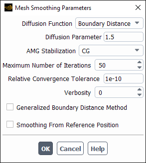
The Mesh Smoothing Parameters dialog box is available by clicking the button in the Smoothing tab of the Mesh Method Settings Dialog Box, and it allows you to define settings for the smoothing method.
Controls
- Spring Constant Factor
controls the spring stiffness.
- Convergence Tolerance
controls the smoothing convergence.
- Maximum Number of Iterations
specifies the maximum number of iterations that will be attempted.
- Elements
controls the elements where spring-based smoothing is applied.
- Tet in Tet Zones
(3D only) specifies that only cell zones with all tetrahedral elements get smoothed.
- Tet in Mixed Zones
(3D only) specifies that tetrahedral elements in mixed element zones get smoothed.
- Tri in Tri Zones
(2D only) specifies that only cell zones with all triangular elements get smoothed.
- Tri in Mixed Zones
(2D only) specifies that triangular elements in mixed element zones get smoothed.
- All
specifies that all element types get smoothed.
- Laplace Node Relaxation
specifies how the update of the node positions is relaxed on boundaries where there is Laplacian smoothing.
- Verbosity
specifies the level of detail printed to the console during the calculation. Setting this to 1 (for radial basis function smoothing) ensures that the absolute tolerance computed (based on your specified relative tolerance) is printed, or (for all other smoothing methods) ensures that smoothing residuals are printed; alternatively, the default value of 0 suppresses such output.
- Diffusion Function
specifies whether the diffusion coefficient is a function of the Boundary Distance (Equation 13–3) or the Cell Volume (Equation 13–4). This drop-down list is only available for diffusion-based smoothing.
- Diffusion Parameter
specifies
 in Equation 13–3 or Equation 13–4, depending on the selected Diffusion
Function. This number-entry box is only available for diffusion-based
smoothing.
in Equation 13–3 or Equation 13–4, depending on the selected Diffusion
Function. This number-entry box is only available for diffusion-based
smoothing.- AMG Stabilization
selects the algebraic multigrid (AMG) stabilization method used by the linear solver to perform mesh smoothing calculations. This drop-down list is only available for smoothing based on diffusion (when using the finite element method) or the linearly elastic solid model.
- Relative Convergence Tolerance
specifies the relative residual tolerance for smoothing based on diffusion, the linearly elastic solid model, or a radial basis function interpolation.
- Generalized Boundary Distance Method
is an option that is available when you have selected Boundary Distance for the Diffusion Function, and it allows you to use of a “generalized” boundary distance for the diffusion coefficient calculation. When this option is enabled, the calculation uses the normalized distance to the nearest boundary that is not declared as deforming, regardless of type; when it is disabled, only wall boundaries are considered.
- Local Smoothing
limits the amount of the domain that is smoothed to only those cells that are close to the moving boundary zones, to ensure that the mesh away from the moving boundary zones remains undisturbed by the smoothing, and to decrease the computational time required for smoothing. This option is available when the smoothing method is based on a radial basis function interpolation. For details, see Local Smoothing with the Radial Basis Function Smoothing Method.
- Smoothing From Reference Position
enables smoothing from a reference position. Such smoothing may produce greater mesh quality consistency for stationary or moving meshes with periodic or quasi-periodic motion. It is available when the smoothing method is based on diffusion, the linearly elastic solid model, or a radial basis function interpolation; it is not available with layering, remeshing, and/or automatic adaption.
- Poisson’s Ratio
specifies the linearly elastic solid material property
 in Equation 13–12. This number-entry box
is only available for smoothing based on the linearly elastic solid model.
in Equation 13–12. This number-entry box
is only available for smoothing based on the linearly elastic solid model.
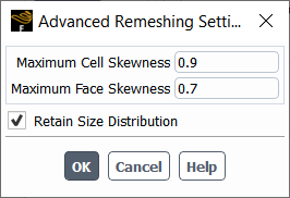
The Advanced Remeshing Settings dialog box allows you to revise the default settings for the Unified Remeshing method. For further details, see Unified Remeshing.
Controls
- Maximum Cell Skewness
defines the maximum cell skewness in the zone.
- Maximum Face Skewness
defines the maximum cell skewness in the surface mesh.
- Retain Size Distribution
enables the use of local size criteria when marking cells for remeshing, in an attempt to maintain the initial mesh size distribution even as the mesh moves. When disabled, cells are instead marked when their length scales are outside of the minimum and maximum length scale values of the cell zone in the initial mesh. Either marking can be overridden if more restrictive values are specified using the
define/dynamic-mesh/controls/remeshing-parameters/length-minanddefine/dynamic-mesh/controls/remeshing-parameters/length-maxtext commands.
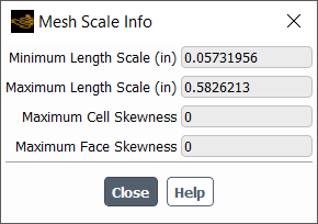
The Mesh Scale Info dialog box allows you to inspect the values of minimum and maximum length scale and maximum cell/face skewness in a mesh.
Controls
- Minimum Length Scale
displays the minimum length scale in the mesh.
- Maximum Length Scale
displays the maximum length scale in the mesh.
- Maximum Cell Skewness
displays the maximum cell skewness in the zone.
- Maximum Face Skewness
displays the maximum cell skewness in the surface mesh.
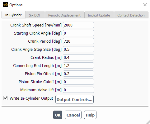
The Options dialog box allows you to set the parameters for the options available in the Options group box of the Dynamic Mesh task page.
Controls
- In-Cylinder
contains parameters to be specified for the in-cylinder model. See In-Cylinder Settings for more information.
- Crank Shaft Speed
specifies the speed of the crank shaft.
- Starting Crank Angle
specifies the starting crank angle.
- Crank Period
specifies the crank period.
- Crank Angle Step Size
specifies the crank angle step size used to determine the time step size to advance the solution.
- Crank Radius
specifies the crank radius to calculate the piston location.
- Piston Pin Offset
specifies the perpendicular offset of the piston pin from the plane defined by the crank shaft axis and the direction of motion of the piston. The sign of this value is positive if top-dead-center (TDC) occurs prior to a crank angle of 0°.
- Connecting Rod Length
specifies the length of the connecting rod.
- Piston Stroke Cutoff
specifies the piston stroke cutoff used to control the onset of layering in the cylinder chamber.
- Minimum Valve Lift
specifies the minimum valve lift.
- Write In-Cylinder Output
enables or disables the writing of in-cylinder specific output parameters. When this option is enabled, the button becomes active.
- Output Controls...
displays the In-Cylinder Output Controls Dialog Box and is available only after the Write In-Cylinder Output option is enabled.
- Six DOF
contains parameters to be specified for the six degrees of freedom (DOF) solver. See Six DOF Solver Settings for more information.
- Six DOF Properties
displays a list of defined sets of six DOF properties.
- Create/Edit...
opens the Six DOF Properties Dialog Box.
- Delete
removes the selected set of six DOF properties from the Six DOF Properties list.
- Delete All
removes all sets of six DOF properties from the Six DOF Properties list.
- Gravitational Acceleration
contains the text entry boxes for gravitational acceleration in X, Y, and Z directions.
- X, Y, Z
specifies the gravitational acceleration in X, Y, and Z directions respectively.
- Write Motion History
allows you to keep track of an object’s motion history.
- File Name
allows you to specify a file name for saving the object’s motion history.
- Periodic Displacement
contains parameters to be specified for periodic displacement in blade flutter analysis. See Defining the Periodic Displacement of the Blades for more information.
- Periodic Displacement Groups
lists the currently available periodic displacement groups.
- Create
creates a new periodic displacement group.
- Edit
edits an existing periodic displacement group.
- Delete
deletes an existing periodic displacement group.
- Delete All
deletes all existing periodic displacement group.
- Implicit Update
contains parameters to be specified for implicit mesh updating. See Implicit Update Settings for more information.
- Update Interval
allows you to specify the frequency in iterations at which the mesh will be updated within a time step.
- Motion Relaxation
allows you to set a value (within the range of 0 to 1) for
 in Equation 13–29, which defines the relaxation of
the motion (that is, displacement of the nodes) during the mesh update.
in Equation 13–29, which defines the relaxation of
the motion (that is, displacement of the nodes) during the mesh update.- Residual Criteria
allows you to set the relative residual threshold that is used to check the motion convergence.
- Contact Detection
contains parameters to be specified for contact detection. See Contact Detection Settings for more information.
- Face Zones
allows you to select the face zones that will be involved in contact detection.
- Proximity Threshold
allows you to set the threshold below which the user-defined function and/or flow control settings for contact detection will be invoked.
- UDF
allows you to specify the user-defined function that will be invoked when contact has been detected.
- Contact Region
contains controls that affect the flow in contact regions.
- Flow Control
allows you to indicate whether you want the flow conditions to change for cells adjacent to faces zones that fall below the Proximity Threshold distance.
- Settings...
opens the Flow Control Settings Dialog Box, where you can define flow control settings for the contact regions.
- Update Contact Marks
updates which cells are marked in order to block flow in the contact region, using the current Proximity Threshold value. This button is only available when the Contact Marks method is selected in the Flow Control Settings Dialog Box.
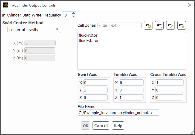
The In-Cylinder Output Controls dialog box contains parameters that control the output for the in-cylinder model. See In-Cylinder Settings for more information.
Controls
- In-Cylinder Data Write Frequency
represents an integer entry specifying the interval in number of time-steps. Make sure that a value other than 0 is used for the frequency, in order to allow you to complete your setup.
- Swirl Center Method
contains a drop-down list that allows you to select the method to calculate the swirl center. The list contains center of gravity and fixed, with center of gravity being the default value.
- center of gravity
calculates the swirl center inside the code and is used as the center of gravity of the chosen cell zones.
- fixed
enables you to specify a swirl center in the X, Y, and Z entry fields below the drop-down list.
In addition to these two options, you can chose to use your own Compiled user-defined function to calculate the swirl center. For details on using a dynamic mesh UDF, see the separate Fluent Customization Manual.
- Cell Zones
is a list that displays the names of all existing cell zones in the case files. You can select only the zones relevant for the swirl and tumble calculations.
- Swirl Axis
specifies the swirl axis with three entries for the directional components. By default, X, Y, Z= 0, 1, 0.
- Tumble Axis
specifies the directional components of Tumble Axis in X, Y, Z directions. By default, X, Y, Z = 0, 0, 1. This applies only in 3D.
- Cross Tumble Axis
specifies the directional components of Cross Tumble Axis in X, Y, Z directions. By default, X, Y, Z = 1, 0, 0. This applies only in 3D.
- File Name
specifies the name of the In-Cylinder output file. By default, the file name contains the name of the case file appended with a
.txtextension.
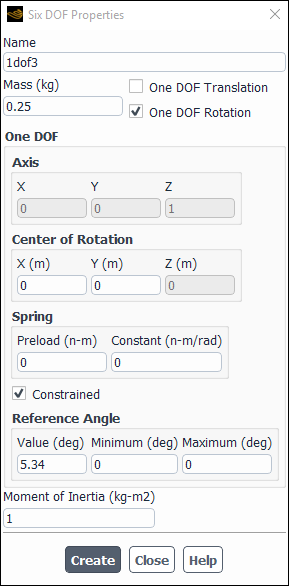
The Six DOF Properties dialog box allows you to define a set of properties for a rigid body dynamic object that uses the Six DOF solver. The set of properties that you create can then be selected in the Six DOF UDF/Properties drop-down in the Dynamic Mesh Zones Dialog Box for the zones that make up the object. See Setting Rigid Body Motion Attributes for the Six DOF Solver and Rigid Body Motion for more information.
Controls
- Name
specifies the name of the set of properties, which will be selectable in the Six DOF UDF/Properties drop-down in the Dynamic Mesh Zones Dialog Box.
- Mass
defines the mass of the rigid body dynamic object.
- One DOF Translation
specifies that the dynamic object will only undergo one DOF translation.
- One DOF Rotation
specifies that the dynamic object will only undergo one DOF rotation.
- One DOF
contains settings that define the one DOF translation or rotation.
- Direction
defines the vector along which the object will be allowed to translate.
- Axis
defines the components of the axis of rotation. Note that for 2D cases, the axis will be either the positive or negative z direction, depending on the sign of the value you enter for Z.
- Center of Rotation
defines the point about which the object rotates. Note that this center of rotation can be different than the Center of Gravity defined in the Dynamic Mesh Zones Dialog Box.
- Spring
contains settings that define an optional Hooke's law spring that can exert forces / torques on the object. It is a compression / extension spring for translations, and it is a torsion spring for rotations.
- Preload
defines a spring load that is constantly applied to the object, in addition to the loading resulting from the spring Constant. The Preload can be a positive or negative value, and is defined relative to the Direction (for translation) or the Axis (for rotation).
- Constant
defines the spring constant / rate.
- Constrained
specifies that the range of motion of the object is limited, as defined by the settings in the Reference Point group box (for translation) or the Reference Angle group box (for rotation).
- Reference Point
contains settings that define the limits of the object's translation when the Constrained option is enabled.
- Location
assigns a coordinate value to a point located on the object in its initial position; the Minimum and Maximum coordinates are then defined relative to this value along the Direction vector, in order to establish the limits of translation.
- Minimum
defines the lower extent of the constrained translation along the Direction vector, relative to the Location.
- Maximum
defines the upper extent of the constrained translation along the Direction vector, relative to the Location.
- Reference Angle
contains settings that define the limits of the object's rotation when the Constrained option is enabled.
- Value
assigns an angular coordinate value to the orientation of the object in its initial position; the Minimum and Maximum angles are then defined relative to this orientation about the axis of rotation, in order to establish the limits of rotation.
- Minimum
defines the lower extent of the constrained rotation about the axis of rotation, relative to the Value.
- Maximum
defines the upper extent of the constrained rotation about the axis of rotation, relative to the Value.
- Moment of Inertia
defines the moment of inertia for the rigid body dynamic object that undergoes one degree of freedom (DOF) rotation. Note that the values are relative to the Center of Rotation and Axis settings.
- Inertia Tensor
defines the components of the inertia tensor for the object during six DOF motion. Note that the values are relative to the Center of Gravity and Rigid Body Orientation settings defined in the Dynamic Mesh Zones Dialog Box.
The Periodic Displacement Group dialog box allows you to quickly run different mode shapes by having different displacements activated under each group. See Defining the Periodic Displacement of the Blades for more information.
Controls
- Name
specifies the name of the periodic displacement group.
- Motion
currently the only option is Prescribed with None (no wave), Travelling Wave Method, or Influence Coefficient Method.
- Wave Direction
(only with Travelling Wave Method) specifies the direction of the wave as Forward or Backward.
- Nodal Diameter
(only with Travelling Wave Method) specifies the vibration of the blades with Interblade Phase Angle (IBPA) which results in a traveling wave pattern. For complex mode shapes that are generated with cyclic symmetry, the mode shape profile is already phase-shifted so the IBPA is not needed. For real only mode shapes, you must supply information about the IBPA.
- Periodic Displacement Properties
allows the definition of multiple periodic displacements.
- Create
creates a new periodic displacement.
- Copy
creates a copy of an existing periodic displacement.
- Edit
edits an existing periodic displacement.
- Activate
activates a periodic displacement for the current run. The
(active)suffix will appear next to the currently active displacement.- Delete
deletes a periodic displacement.
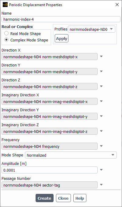
The Periodic Displacement Properties dialog box allows specify periodic displacement for an aerodynamic damping calculation. See Defining the Periodic Displacement of the Blades for more information.
Controls
- Name
specifies the name of the periodic displacement.
- Real or Complex
specifies the mode shape as real or complex.
- Profiles
enables you to apply a displacement profiles to the appropriate fields.
- Direction X,Y,Z
specifies the real displacement components typically using a mode shape profile.
- Imaginary Direction X,Y,Z
(only available for Complex mode shape) specifies the imaginary displacement components typically using a mode shape profile.
- Frequency
specifies the mode shape frequency.
- Mode Shape
specifies whether the mode shape is Normalized or Non-normalized.
- Amplitude
specifies the amplitude for normalized mode shapes to obtain the maximum modal displacement.
- Scaling
specifies the scaling parameter for non-normalized mode shapes to scale the displacement vectors.
- Passage Number
specifies the sector tag, typically from the mode shape profile.
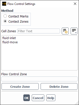
The Flow Control Settings dialog box allows you to define flow control settings for the contact regions. See Contact Detection Settings for more information.
Controls
- Method
allows you to select how the flow is controlled when contact is detected.
- Contact Marks
specifies that cells in the contact region are marked and then treated with boundary zone conditions that block the flow.
- Contact Zones
specifies that cells in the contact regions are separated into new cell zones that have revised physical properties (for example, inertial and/or viscous porous resistance) that restrict the flow. The physical properties are copied from the respective flow control zones, which are created using the other controls in this dialog box.
- Solution Stabilization
enables the performance of additional iterations per time step and the application of solution controls to improve the stability of the solver during contact, as part of the contact marks method.
- Cell Zones
selects a cell zone that provides the initial physical properties of a flow control zone.
- Flow Control Zone
specifies a new name for or displays the existing name of a flow control zone for the selection in the Cell Zones list.
- Create Zone
creates a flow control zone (based on the selection from the Cell Zones list, with the Porous Zone option enabled), and opens the Fluid dialog box so you can revise the settings to better represent the restricted flow.
- Delete Zone
deletes the current Flow Control Zone.
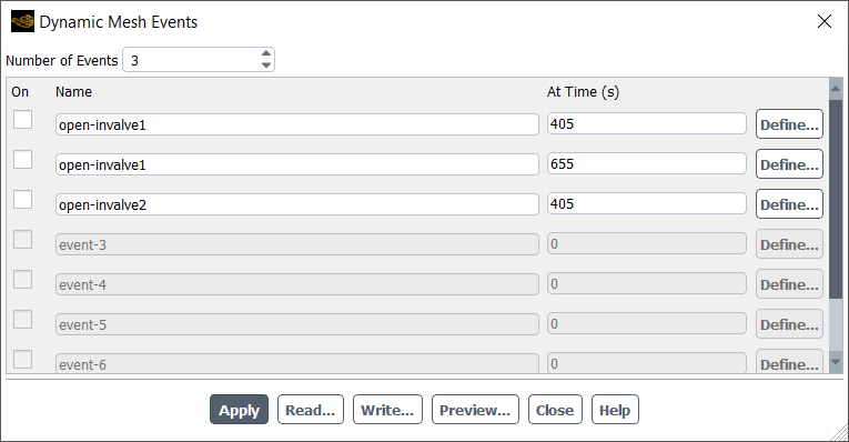
The Dynamic Mesh Events dialog box is available to control the timing of specific events during the course of the simulation. See Defining Dynamic Mesh Events for details.
Controls
- Number of Events
specifies the number of events to be defined.
- On
enables the corresponding event.
- Name
specifies the name of the event.
- At Crank Angle
specifies the angular location of the crank at which the event should occur. This option appears for in-cylinder flows.
- At Time
specifies the time (in seconds) at which you want the event to occur. This option appears for non-in-cylinder flows.
- Define...
opens the Define Event Dialog Box.
- Read...
opens The Select File Dialog Box.
- Write...
opens The Select File Dialog Box.
- Preview...
opens the Events Preview Dialog Box.
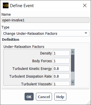
The Define Event dialog box allows you to define events.
Controls
- Name
contains the name of the event to be defined.
- Type
specifies the type of event. You can choose the type of event from the drop-down list. These event types and their definitions are described in Events.
- Definition
contains the input parameters corresponding to the type of event selected under Type.
- Zone
contains a selectable list of the zones. The selection specifies the name of the zone(s) to be changed. This item will appear only for the Change Zone Type event.
- New Zone Type
specifies the type of zone to which an existing zone must be changed. This item will appear only for the Change Zone Type event.
- From Zone
specifies the name of the zone from which the boundary condition is to be copied. This item will appear only for the Copy Zone BC event.
- To Zone(s)
specifies the name of the zone to which the boundary condition is to be copied. This item will appear only for the Copy Zone BC event.
- Zone(s)
contains a selectable list of the zones. The selection specifies the name of the zone to be activated/deactivated. This item will appear only for the Activate Cell Zone and Deactivate Cell Zone events.
- Interface Name
contains the name of the interface to be created or deleted. This item will appear only for the Create Sliding Interface and Delete Sliding Interface events.
- Interface Zone 1, Interface Zone 2
specifies the two zones on either side of the interface to be created. This item will appear only for the Create Sliding Interface event.
- Wall 1 Motion, Wall 2 Motion
specifies the dynamic zones whose motion can be copied for the zones specified under Interface Zone 1 and Interface Zone 2. This item will appear only for the Create Sliding Interface event.
- Attribute
allows you to select the relevant motion attribute. This item will appear only for the Change Motion Attribute event.
- Status
allows you to enable or disable the motion attribute. This item will appear only for the Change Motion Attribute event.
- Dynamic Mesh Zones
contains a list of dynamic zones. This item will appear only for the Change Motion Attribute event.
- Crank Angle Step Size
specifies the new physical time step size in degrees. This item will appear only for the Change Time Step Size event.
- Base Dynamic Zone
specifies the zone from which the layer of cells is to be created. This item will appear only for the Insert Boundary Layer and Remove Boundary Layer event.
- Side Dynamic Zone
represents the deforming face zone adjacent to the Base Dynamic Zone before the layer is inserted. This item will appear only for the Insert Boundary Layer event.
- Internal Zone 1 Name, Internal Zone 2 Name
specifies the name of the new internal zones.
- Time Step Size
allows you to change the time step size of the event. This item will appear only for the Change Time Step Size event.
- Under-Relaxation Factors
allows you to specify the under-relaxation factors for the selected event. This item will appear only for the Change Under-Relaxation Factors event. See Setting Under-Relaxation Factors for details.
- Adjacent Dynamic Face Zone
allows you to select the dynamic face zone adjacent to the location of the cell layer to be inserted (or deleted). You can select the required zone from the drop-down list.
- Direction Parameter
is the direction with respect to the selected dynamic face zone a layer of cells is removed or added.
- Command
specifies the series of text / Scheme commands or the macro to be executed during the simulation. This item will appear only for the Execute Command event.
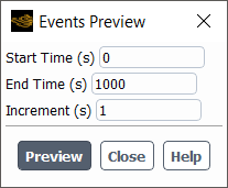
The Events Preview dialog box allows you to play the events to check that they are defined correctly.
Controls
- Start Crank Angle
specifies the crank angle at which you want to start the preview (for in-cylinder flows).
- Start Time
specifies the time at which you want to start the preview (for non-in-cylinder flows).
- End Crank Angle
specifies the crank angle at which you want to end the preview (for in-cylinder flows).
- End Time
specifies the time at which you want to end the preview (for non-in-cylinder flows).
- Increment
specifies the size of the step to take during the preview.
- Preview
plays back the events at the crank angle specified for each event and reports when each event occurs in the text (console) window.
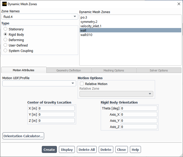
The Dynamic Mesh Zones dialog box allows you to specify the motion of the dynamic zones in your model. See Specifying the Motion of Dynamic Zones for details.
Controls
- Zone Names
contains the names of the zones in the model.
- Type
contains the types of motion that can be specified for a dynamic zone.
- Stationary
explicitly declares the zone as stationary, so that the nodes on this zone are excluded when updating the node positions. See Specifying the Motion of Dynamic Zones for more information.
- Rigid Body
specifies the zone as having a rigid-body motion.
- Deforming
specifies the zone as deforming.
- User-Defined
enables you to specify a user-defined zone motion.
- System Coupling
allows the zone to be involved in a system coupling simulation where the motion is defined by the application that Ansys Fluent is coupled with on this zone (see the Fluent in Workbench User's Guide and the System Coupling User's Guide for more details). Once enabled, the Solver Options tab can be used to help achieve convergence for system coupling cases where the physics is strongly coupled. If a dynamic mesh zone of the type System Coupling exists, and Ansys Fluent is not involved in a system coupling simulation, then this zone type behaves in the same way as a stationary zone.
- Intrinsic FSI
specifies that a wall zone between a fluid and solid cell zone deforms according to the deformation of the adjacent solid zone as part of a two-way intrinsic fluid-structure interaction (FSI) simulation. Note that this type can only be used for the side of a two-sided wall (that is, the wall or wall-shadow) that is immediately adjacent to the fluid cell zone (as indicated by the Adjacent Cell Zone field in the Wall dialog box). This option is only available when a model is selected in the Structural Model Dialog Box.
- Dynamic Mesh Zones
lists all of the dynamic zones in the case.
- Motion Attributes
contains parameters to specify the motion attributes for a rigid-body-motion zone, a deforming-motion zone, or a user-defined-motion zone.
- Motion UDF/Profile
allows you to define the motion of the rigid body zone by selecting a motion definition, profile, or user-defined function from the drop-down list. Note that the names of motion definitions are preceded by motion:: in this list. See Managing Motion Definitions for information about motion definitions, see Profiles and Solid-Body Kinematics for information on profiles, and see the Fluent Customization Manual for information on user-defined functions.
- Six DOF UDF/Properties
allows you to define the motion of a rigid body zone by selecting a profile, user-defined function, or set of six DOF properties (created using the Six DOF Properties Dialog Box) from the drop-down list. This option is available only when On is enabled in the Six DOF group box.
- Six DOF
contains parameters for the Six DOF solver.
- On
enables the use of the Six DOF solver.
- Passive
(if enabled) does not take forces and moments on the zone into consideration.
- Center of Gravity Location
specifies the initial values of the coordinates for the location of the center of gravity of the selected zone. This item will appear only if the motion Type is Rigid Body and In-Cylinder is not enabled in the Dynamic Mesh task page. After calculating, Ansys Fluent updates these fields, allowing you to keep track of the object's current location.
- Motion Options
provides a Relative Motion option, which allows you to specify that the motion of the dynamic zone is relative to another pre-defined rigid body zone. This group box will only appear if the Type is Rigid Body or User-Defined; for the latter, the Relative Zone must be a cell zone.
- Rigid Body Orientation
specifies the initial values that define the orientation of the rigid body of the selected zone. This item will appear only if the motion Type is Rigid Body and In-Cylinder is not enabled in the Dynamic Mesh task page. After calculating, Ansys Fluent updates these fields, allowing you to keep track of the object's current orientation. The rigid body orientation is used, if needed, by the six DOF solver to evaluate the external load forces and moments (see
DEFINE_SDOF_PROPERTIESin the Fluent Customization Manual), as well as when evaluating the relative motion of a dynamic zone with respect to another (seeDEFINE_CG_MOTIONin the Fluent Customization Manual).- Center of Gravity Velocity
specifies the velocity of the center of gravity with respect to inertia coordinate system. This option is available only if the Six DOF solver is the selected model.
- Rigid Body Angular Velocity
specifies the angular velocity of the rigid body with respect to inertia coordinate system. This option is available only if the Six DOF solver is the selected model.
- Lift/Stroke
contains the current value of valve lift or piston stroke, which is automatically updated when you click Create. This item will appear only if In-Cylinder is enabled in the Dynamic Mesh task page.
- Valve/Position Axis
specifies the direction of the reference axis of the valves or piston for an in-cylinder problem. This item will appear only if In-Cylinder is enabled in the Dynamic Mesh task page.
- Mesh Motion UDF/Profile
allows you to select the user-defined function that defines the geometry and motion of the zone. This item will appear only if the motion Type is User-Defined.
- Exclude Mesh Motion in Boundary Conditions
allows you to specify whether the boundary mesh motion is excluded in the physical boundary conditions of that zone. This option is only available for non-periodic boundary zones.
- Geometry Definition
contains parameters to define a deforming zone.
- Definition
allows you to select a geometry definition to project nodes of the deforming zone on. Available options are faceted, plane, cylinder, and user-defined. When the linearly elastic solid mesh smoothing method or the radial basis function smoothing method is enabled (see Linearly Elastic Solid Based Smoothing Method or Radial Basis Function Smoothing, respectively), you also have the option of selecting unspecified. If you have created auxiliary geometry definitions (as described in Managing Auxiliary Geometry Definitions), the names of the supported definitions will be available for selection in the list preceded by geom::.
- Feature Options
allows you to preserve features for 3D cases on boundary zones of type Deforming or User-Defined. Such features may be at the juncture of different boundary zones, or they may be on a single non-planar boundary zone.
- Feature Detection
enables the detection and preservation of features of a particular angular range.
- Feature Angle
defines a threshold value in degrees. For details on how this angle is defined, see Feature Detection.
- Point on Plane
allows you to specify the position of a point on the plane. This item will appear only when you select plane for the Definition.
- Plane Normal
allows you to specify the direction of the plane normal. This item will appear only when you select plane for the Definition.
- Cylinder Radius
allows you to specify the radius of the cylinder. This item will appear only when you select cylinder for the Definition.
- Cylinder Origin
allows you to specify the location of the cylinder origin. This item will appear only when you select cylinder for the Definition.
- Cylinder Axis
allows you to specify the direction of the cylinder axis. This item will appear only when you select cylinder for the Definition.
- Geometry UDF
allows you to select a user-defined function for a geometry Definition.
- Meshing Options
contains parameters for various meshing options.
- Adjacent Zone
contains the name of the adjacent zone that is involved in local remeshing or dynamic layering. This item will appear only if the zone type is Stationary, Rigid Body, User-Defined, or Intrinsic FSI.
- Cell Height
allows you to specify the ideal height of the adjacent cells as either a constant value or a compiled user-defined function. This item will appear only if the motion Type is Stationary, Rigid Body, User-Defined, or Intrinsic FSI.
- Deform Adjacent Boundary Layer with Zone
enables the smoothing of an adjacent boundary layer mesh. This option is not available when Stationary or Deforming is selected in the Type list.
- Remeshing
enables remeshing for a deforming zone, and allows you to use the settings in the group box below to specify whether the global settings defined in the Remeshing tab of the Mesh Method Settings Dialog Box are applied to this zone. The settings that are available in the group box are based on whether you are defining a boundary zone or a cell zone, and on the global remeshing settings.
- Parameters
provides remeshing settings for boundary zones or cell zones.
- Global Settings
allows you to specify that this deforming zone uses the settings you defined globally in the Remeshing tab of the Mesh Method Settings dialog box. When this option is disabled, you can use the other settings under Parameters to define unique local remeshing criteria.
- Minimum Length Scale
specifies the lower limit of cell size below which the cells are marked for remeshing for the zone.
- Maximum Length Scale
specifies the upper limit of cell size above which the cells are marked for remeshing for the zone.
- Maximum Skewness
specifies the desired value for maximum skewness in the zone.
- Zone Scale Info...
opens the Zone Scale Info Dialog Box, in which you can view the statistics of the zone, such as minimum, maximum, and average length scale values, as well as the maximum skewness.
- Options
provides remeshing options for the zone. This group box is only available if you have selected Methods-Based Remeshing in the Remeshing tab of the Mesh Method Settings Dialog Box.
- Region
enables the region-based remeshing method for boundary zones.
- Local
enables the local face remeshing method for boundary zones.
- Smoothing
enables smoothing for a deforming zone, and allows you to use the settings in the group box below to specify whether the global settings defined in the Smoothing tab of the Mesh Method Settings Dialog Box dialog box and the Mesh Smoothing Parameters Dialog Box are applied to this zone. The settings that are available in the group box are based on whether you are defining a boundary zone or a cell zone, and on the global smoothing settings.
- Elements
allows you to specify the element types for which spring-based smoothing is used in this zone. This will only be available if you are defining a cell zone and the Spring/Laplace/Boundary Layer method has been selected in the Smoothing tab of the Mesh Method Settings dialog box.
- Global Settings
allows you to specify that this deforming zone smooths the element types you specified globally in the Mesh Smoothing Parameters Dialog Box. When this option is disabled, you can make a unique local selection using the radio buttons below.
- Tet in Tet Zones
(3D only) specifies that this zone will get smoothed only if it consists entirely of tetrahedral elements.
- Tet in Mixed Zones
(3D only) specifies that all tetrahedral elements in this zone should get smoothed. All other elements in a mixed element zone will not undergo smoothing.
- Tri in Tri Zones
(2D only) specifies that this zone will get smoothed only if it consists entirely of triangular elements.
- Tri in Mixed Zones
(2D only) specifies that all triangular elements in this zone should get smoothed. All other elements in a mixed element zone will not undergo smoothing.
- All
specifies that all element types in this zone will get smoothed.
- Methods
allows you to specify the smoothing method for the zone. This is only available if you are defining a boundary zone and the Spring/Laplace/Boundary Layer method has been selected in the Smoothing tab of the Mesh Method Settings dialog box.
- Spring
enables the spring-based smoothing method for this zone.
- Laplace
enables the Laplacian smoothing method for this zone.
- Remeshing Method
provides settings for local face remeshing of the dynamic zone. This group box will appear only for boundary zones, when the motion Type is User-Defined.
- Local
enables local face remeshing for the dynamic zone. This option is only available when Unified Remeshing is selected or Local Face is enabled in the Remeshing tab of the Mesh Method Settings Dialog Box.
- Maximum Skewness
is a field that, if revised (with a reasonable value), sets a maximum skewness for the local face remeshing of the dynamic zone that is different than the global value set in the Remeshing tab of the Mesh Method Settings Dialog Box.
- Solver Options
contains settings that may help convergence for boundary zones in cases that involve strong fluid-structure interaction (notably zones undergoing rigid body motion with the six degrees of freedom solver, system coupling motion, or two-way intrinsic FSI motion). See Solution Stabilization for Dynamic Mesh Boundary Zones for more information.
- Solution Stabilization
enables/disables solution stabilization settings for boundary zones.
- Stabilization Parameters
contains options for solution stabilization settings.
- Scale Factor
allows you to set the scale factor used by the selected Method for convergence stabilization.
- Method
Stabilization is achieved through a boundary source coefficient introduced in the continuity equation. It is designed to improve the diagonal dominance of the matrix system in the cells adjacent to the boundary zone. Two methods for this boundary source coefficient are available:
- volume-based
specifies that the diagonal entry of the linear matrix system corresponding to the discretized continuity equation is re-scaled using the cell volume and a scale factor, according to Equation 13–32.
- coefficient-based
(default) specifies that the diagonal entry of the linear matrix system corresponding to the discretized continuity equation is directly re-scaled by a scale factor, according to Equation 13–33.
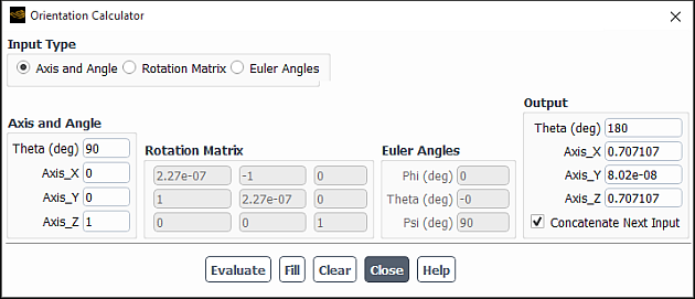
The Orientation Calculator dialog box allows you to convert rotation matrices and Euler angles to axis and angle format. It also allows you to concatenate rotations to determine a rigid body’s final orientation. The output of this calculator can then be used to fill in the initial rigid body orientation of your rigid body motion dynamic zone, which can be used to track the orientation during the calculation.
Controls
- Input Type
allows you to select which method you will use to enter your rigid body orientation values. For additional information about these input types, see Rigid Body Motion.
- Axis and Angle
allows you to enter the angle of rotation and the axis about which the rigid body is rotating.
- Rotation Matrix
allows you to enter the orientation of the rigid body as a rotation matrix.
- Euler Angles
allows you to enter the orientation of the rigid body as a set of Euler Angles. For an explanation of which Euler angles method Fluent uses, see Rigid Body Motion.
- Output
displays the angle of rotation and the axis about which the rigid body is rotating after you click .
Note that if you enter a single orientation in Axis and Angle and click , the values shown in Output will be the same as you entered in Axis and Angle
- Concatenate Next Input
concatenates the next input entered (after clicking ) to the values displayed in Output
- Evaluate
converts the specified input values into angle and axis format and displays the results in Output.
Note that the calculator also converts the entered values into the other two “grayed-out” input formats.
- Fill
enters the values displayed in Output into the Rigid Body Orientation fields of the Dynamic Mesh Zones dialog box.
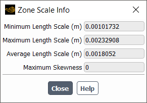
The Zone Scale Info dialog box allows you to inspect the values of minimum and maximum cell area or volume, and maximum cell skewness in a zone.
Controls
- Maximum Length Scale
displays the maximum cell length in the zone.
- Minimum Length Scale
displays the minimum cell length in the zone.
- Average Length Scale
displays the average cell length in the zone.
- Maximum Skewness
displays the maximum cell skewness in the zone.
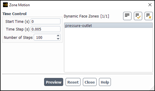
The Zone Motion dialog box will display the motion of zones specified with Rigid Body or User-Defined motion. See Previewing the Dynamic Mesh for details about the items below.
Controls
- Time Control
contains controls to specify the time intervals at which to display the motion.
- Start Time (s)
specifies the time from which to start the zone motion preview.
- Time Step (s)
specifies time step size for zone motion preview.
- Number of Steps
specifies number of time steps for zone motion preview.
- Dynamic Face Zones
allows you to select the dynamic face zones to preview. Only User-Defined or Rigid Body zones are available.
- Preview
previews the zone motion.
- Reset
resets the zone display and the dialog box inputs.
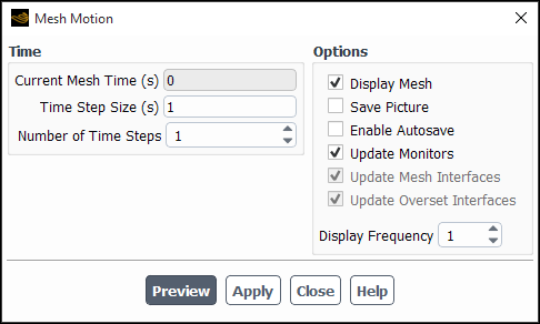
The Mesh Motion dialog box allows you to preview the dynamic mesh as it changes with time before you start your simulation. See Previewing the Dynamic Mesh for details.
Controls
- Time
contains the parameters to specify the time interval at which to update the mesh.
- Current Mesh Time
displays the current time after the dynamic mesh has been advanced the specified number of steps.
- Time Step Size
specifies the size of each time step.
- Number of Time Steps
specifies the number of time steps.
- Options
contains options to view the updated mesh.
- Display Mesh
displays the mesh.
- Save Picture
opens the Save Picture Dialog Box, allowing you to save a picture file of the mesh each time Ansys Fluent updates it during the mesh preview.
- Enable Autosave
opens the Autosave Case During Mesh Motion Preview Dialog Box, allowing you to save the case and data files with the specified name and frequency. See Automatic Saving of Case and Data Files for details.
- Update Mesh Interfaces
allows you to update the interface at every time step.
- Update Monitors
allows you to disable the processing of monitors and computation activities during mesh motion preview.
- Display Frequency
displays the frequency at which Ansys Fluent will update the mesh display.
- Preview
allows you to preview the motion of the selected zones in the graphics window.
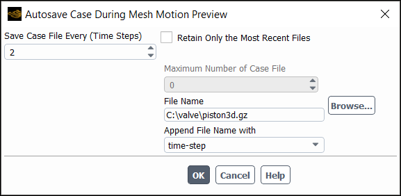
The Autosave Case During Mesh Motion Preview dialog box allows you to automatically save your case during the dynamic mesh preview as it changes with time, while running your simulation. See Automatic Saving of Case and Data Files for details about the inputs.
Controls
- Save Case File Every
contains the parameters to specify the time interval at which to update the mesh.
- Retain Only the Most Recent Files
allows you to restrict the number of files saved by Ansys Fluent if you have limited disk space. When this option is enabled, you can enter the appropriate value in the Maximum Number of Data Files field.
Note: Only the associated case files are retained when using this option.
- Maximum Number of Data Files
specifies the maximum number of data files that can be saved at any instance. If you have constraints on the disk space, you can restrict the number of files to be saved using this field. After saving the specified number of files, Ansys Fluent will overwrite the earliest existing file. The default value for this field is zero, which saves all the files.
- Append File Name with
allows you to select flow-time or time-step to be appended to the file name. This option is available only for unsteady-state calculations. The default selection is flow-time.