This chapter describes how to create and manage motion definitions, which can be useful for rigid body dynamic mesh zones (as described in Rigid Body Motion). A motion definition is comprised of a name, reference frame, translation definition, and rotation definition. When defining the rigid body motion of the dynamic zone, using a motion definition may be advantageous, as it can be simpler to set up than the alternatives (that is, a profile or user-defined function) and allows you to use expressions to define the dynamic mesh motion.
To manage motion definitions, perform the following steps:
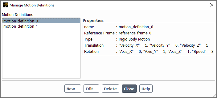
Open the Manage Motion Definitions dialog box from the Outline View.
 Setup → Motion
Definitions
Setup → Motion
Definitions Manage...
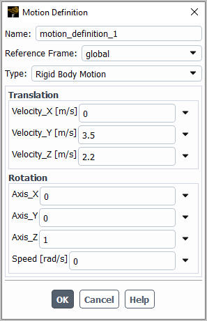
 Click the button in the Manage Motion Definitions dialog box to open the Motion Definition dialog box.
Enter a suitable Name for the definition.
Make a selection from the Reference Frame drop-down list to define the reference frame for the motion. You can use the default global reference frame, or select a local reference frame definition that you have previously set up, as described in Reference Frames.
Make a selection from the Type drop-down list to specify the kind of motion you are defining. The Rigid Body Motion selection is the only available option.
Define the translation velocity components in the coordinate directions using the fields in the Translation group box. You can define Velocity_X, Velocity_Y, and (for 3D cases) Velocity_Z components. These can be defined as a constant value, an expression, an input parameter, or a named expression.
Define the rotation using the fields in the Rotation group box. For 3D cases, you can define the rotation axis components in the coordinate directions through the Axis_X, Axis_Y, and Axis_Z fields; for 2D cases, the axis direction is the positive Z direction. Then you can provide a value for the Speed, which is defined using the right-hand rule with respect to the defined axis. Each of these fields can be defined as a constant value, an expression, an input parameter, or a named expression.
Click to save your settings and close the Motion Definition dialog box.
Repeat the previous step to add additional motion definitions.
After you have created motion definitions, you can use the Manage Motion Definitions dialog box to take further actions. If you select a definition from the Motion Definitions list, details are displayed under Properties. You can then take the following actions:
To revise the selected definition, click the button and change the setup using the Motion Definition dialog box that opens.
To delete the selected definition, click the button.