


The following sections describe the CMS generation pass:
The process for generating a CMS superelement consists of two primary tasks:
Building the model
This step is identical to building the model for a substructuring analysis. Define density (DENS)--or mass in some form--because CMS must generate both stiffness and mass matrices.
Creating the superelement matrices
The "solution" from a CMS generation pass consists of the superelement matrices (reduced stiffness and mass matrices or reduced stiffness, mass, and damping matrices). This flowchart illustrates the process necessary for creating the superelement matrix file:
Specifying the CMS method — When specifying the CMS method, also specify the number of modes and, optionally, the frequency range used to generate the superelement. The program supports the fixed-interface (CMSOPT,FIX), free-interface (CMSOPT,FREE), and residual-flexible free-interface (CMSOPT,RFFB) CMS methods. If using the free-interface method, also specify the rigid body modes (CMSOPT,,,,
Fbddef). If using the residual-flexible free-interface method, specify pseudo-constraints (D,,,SUPPORT).If groups of repeated frequencies are present, make sure you extract all the solutions in each group. For more information, see Repeated Eigenvalues in the Theory Reference.
Specifying the mode-extraction method — The default method is Block Lanczos (
Eigmeth= LANB on the CMSOPT command). The Subspace and Supernode methods are also supported. See Comparing Mode-Extraction Methods in the Structural Analysis Guide for a comparison of the methods. When using the Supernode mode-extraction method (Eigmeth= SNODE), the frequency range specified by theFREQB/FREQEarguments defaults to 0-100 Hz, similar to MODOPT behavior for this eigensolver. Therefore, it is important to properly define the input quantities when using the Supernode method in order to achieve good performance and accuracy.Naming the superelement matrix file — The program assigns the .sub extension to the superelement matrix file name that you specify (SEOPT,
Sename); therefore, the complete file name is Sename.SUB. The default file name is the jobname (/FILNAME).Specifying the lumped mass matrix formulation — Specify the lumped mass matrix formulation (LUMPM) if necessary. For most applications, Ansys, Inc. recommends the default formulation (depending upon the element type); however, for dynamic analyses involving "skinny" structures such as slender beams or very thin shells, the lumped mass approximation typically yields better results.
Defining master degrees of freedom — In a substructure, master degrees of freedom serve as the interface between the superelements or other elements. Define master degrees of freedom (M) at all nodes that connect to non-superelements (
Lab1= ALL), as shown in Example of a Substructuring Application. You must define master degrees of freedom even if you intend to have no elements in the model other than a superelement.If constraints (D) or force loads (F) are to be applied in the use pass, master degrees of freedom must be defined at these locations (M). Nevertheless, if using the fixed-interface CMS method (CMSOPT,FIX), apply the load in the generation pass and in the use pass as a load vector to avoid over-constrained fixed-interface normal modes.
If the free-interface (CMSOPT,FREE) or the residual-flexible free-interface (CMSOPT,RFFB) CMS method is used, pseudo-constraints on master degrees of freedom can be specified (
SUPPORT= ON on the M command) so that they are constrained during the mode-extraction analysis.If this superelement is to be transformed (SETRAN) later in the use pass or used in a large-deflection analysis (NLGEOM,ON), all nodes that have master degrees of freedom must have all six degrees of freedom (UX, UY, UZ, ROTX, ROTY, ROTZ) defined and active.
For large deflections, master degrees of freedom are typically defined at the joints of the flexible body and are at the nodes connected to a joint element (MPC184), another rigid or flexible body node, or ground. At least two master degrees of freedom must be defined for each substructure, as the average rotation of the superelement is computed from the average rotation of its master degree of freedom. If only one node is a joint node, then another must be chosen at the free end. See the Multibody Analysis Guide for more details.
Specifying pseudo-constraints — Required for the residual-flexible free-interface method (CMSOPT,RFFB). For each superelement where rigid-body modes exist, specify pseudo-constraints. Apply only the minimum number of displacement constraints (D,,,SUPPORT) necessary to prevent rigid body motion: three constraints (or fewer, depending on the element type) for 2D models and six (or fewer) for 3D models.
Obtaining the CMS generation pass solution — Output from the solution (SOLVE) consists of the superelement matrix file (
Sename.SUB), whereSenameis the file name you assigned (SEOPT).Saving a copy of the database — Saving a copy of the database (SAVE) is necessary because you must work with the same data in the expansion pass. To support running the expansion pass in distributed-memory parallel mode, the database must be saved after solution (SOLVE).
As in a substructure generation pass, you can generate multiple superelement load vectors in a CMS generation pass via multiple SOLVE commands. You can also do so via a restart of the CMS generation pass (ANTYPE,SUBSTR,RESTART).
Nested superelements cannot be generated with a CMS generation pass using the residual-flexible free-interface CMS method.
To calculate one residual vector which is included in the normal modes basis used in the transformation matrix of the three available CMS methods, issue RESVEC,ON in the first load step.
When the Coriolis effect in the stationary reference frame is activated (CORIOLIS,ON,,,ON), the stiffness, mass, and damping matrices are treated as non-symmetric by the sparse solver in the generation pass. This doubles the amount of memory used when compared to symmetric systems. For a model with a large number of degrees of freedom, the memory options for the sparse solver (BCSOPTION) should be set using the guidelines outlined in Direct (Sparse) Solver Memory Usage in the Performance Guide.
If the geometry of the model is cyclic symmetric, the cyclic symmetry or multistage cyclic symmetry procedure can be used. The cyclic reduction is then added to the substructuring reduction to further reduce the number of equations resolved in the superelement use pass.
The following applies for each cyclic procedure:
When cyclic symmetry is active (CYCLIC), a superelement will be generated for each harmonic index and superelement files will be called
SenameHIx.sub, whereSenameis input using SEOPT andxis the harmonic index number. For an example, see Single Cyclic Symmetry Superelement CMS Example. These superelements can only be used during a modal use pass and cannot be expanded.When multistage cyclic symmetry is active (MSOPT,NEW,
SnameandValue2=x), the name of the superelement (Senameon the SEOPT command) must beSname_HIx. For an example, see Single Stage Cyclic Symmetry Superelement CMS Example.
After obtaining the CMS superelement matrices, proceed to the use pass and then the expansion pass, as you would in a substructuring analysis.
For a detailed example of how to use CMS, see Modal Analysis of a 2D Tuning Fork.
The following table describes the different types of component modes that make up the transformation matrix for the three CMS methods, as described in Component Mode Synthesis (CMS) in the Mechanical APDL Theory Reference. It also defines the CST, IRF, NOR, and RSD abbreviations.
Table 3.1: Component Modes Definition (Fix, Free, Free with
Support = ON for some master DOFs)
| FIX | FREE |
FREE with
SUPPORT = ON on some master degrees
of freedom | |
|---|---|---|---|
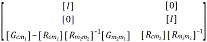
| Constraint mode data (CST) |
where | same as FIX | same as FIX |
| Inertia relief mode data (IRF) | – |
where | – |
| Fixed-interface normal mode data (NOR) |
|
|
where |
| Residual attachment mode data (RSD) | – | – | – |


Table 3.2: Component Modes Definition (RFFB, RFFB with with
Support = ON for some master DOFs)
| RFFB |
RFFB with
SUPPORT = ON on some master degrees
of freedom | |
|---|---|---|
| Constraint mode data (CST) | – | – |
| Inertia relief mode data (IRF) | – | – |
| Fixed-interface normal mode data (NOR) |
where |
where
|
| Residual attachment mode data (RSD) |
|
 |


The modes described in the tables above are written to the
.cms and .tcms files during the
generation pass. The format of these files is described in CMS File Format and TCMS File Format in the
Programmer's Reference. By default the static constraint modes are not written to the
.cms file for the fixed-interface and free-interface
methods. Issue CMSOPT with IOkey = CMS
to write them.
If CMSOPT is issued with IOkey =
TCMS, the transformation matrix is printed out and written to the
.tcms file. The transformation matrix is written only if
OUTPR is issued with ITEM = NSOL
and FREQ≠ NONE.
The following table summarizes the contents of the .cms and .tcms files. It also specifies the degrees of freedom ordering of the component modes. See Degree of Freedom Ordering in the Ansys Parametric Design Language Guide for more information on degree-of-freedom ordering.
Table 3.3: Contents of .cms and .tcms Files and Degree-of-Freedom Ordering According to IOkey Setting
| FIX | FREE | RFFB | |||||
|---|---|---|---|---|---|---|---|
| CST | NOR | CST | IRF | NOR | RSD | NOR | |
| .cms File | Degree-of-freedom ordering: solver | Degree-of-freedom ordering: internal | |||||
IOkey ≠ CMS | No | Yes | No | Yes | Yes | Yes | Yes |
IOkey = CMS | Yes | Yes | Yes | Yes | Yes | Yes | Yes |
| .tcms File | Degree-of-freedom ordering: user | – | |||||
IOkey = TCMS | Yes | Yes | Yes | Yes | Yes | – | – |
By default, in the expansion pass, and for each solution, the expansion of nodal degree-of-freedom displacements is followed by the calculation of element results such as nodal loads, reaction loads, and energies. No element results calculation is performed in the generation pass.
All of the CMS methods support the element results calculation during the generation pass. If element-calculation is enabled (CMSOPT with Elcalc = YES), the element results of the component modes included in the transformation matrix of the CMS method are written to the .cms file and directly combined during the expansion pass. For more information, see Component Mode Synthesis (CMS) in the Theory Reference.
This procedure reduces the computational resources of the expansion pass if both of the following conditions are true:
| The number of solutions to expand is high (typically hundreds). |
| The number of master degrees of freedom is low compared to the total number of degrees of freedom of the substructure model (typically less than 100 master degrees of freedom for a finite element model with 150000 degrees of freedom). |
With this procedure, the available results are:
Element nodal component stresses
Element nodal component elastic strains
Element summable miscellaneous data
Element nodal forces
Element energies
and it has the following limitations:
The element nodal loads are available only if there is at least one load applied during the generation pass.
Reaction forces are available only if degree-of-freedom constraints are specified in the generation pass (generally inadvisable, as the mass matrix is not entirely accounted for in the superelement matrix).
Following a transient analysis or a harmonic analysis use pass, quantities using nodal velocities and nodal accelerations (damping force, inertial force, kinetic energy, etc.) can be computed and postprocessed only if OUTRES was issued in the first load step of the use pass with
DSUBres= ALL.The damping element forces and reaction forces are available if a damping matrix was assembled in the generation pass. Damping results do not take into account the damping added during the use pass.
Equivalent strains are evaluated using
EFFNU= 0.0. Use AVPRIN to set the appropriate Poisson's ratio value.Thermal loads are not supported.
NMISC results are not available.
Strains and stresses of PIPE elements are not available in the expansion pass.
Acoustic elements are not supported in the generation pass.
Linear perturbation analysis substructure generation pass is not supported.
The usage of SETRAN or SESYMM in the use pass is not supported if the original superelement matrix was created with
Elcalc= YES on the CMSOPT command.Nested superelements cannot be generated from an original superelement matrix created with
Elcalc= YES on the CMSOPT command.
If Elcalc = YES on the CMSOPT
command, the factorized matrix files SEname.LNxx are not
required for the expansion pass. Consequently, if restarting the generation pass is
not required, ExpMth can be set to NONE or BCLV on the
SEOPT command to save disk space.