This section describes how to perform postprocessing on the solution results obtained from a cyclic symmetry analysis. The following topics are available:
If you exited the program after obtaining the cyclic symmetry solution, use the database (Jobname.db) that you saved for postprocessing. For more information, see Database Considerations After Obtaining the Solution.
The real (base sector) and imaginary (duplicate sector) parts of the solution reside in the results file. However, the solution does not yet represent the actual displacements, stresses, or reaction forces for any part of the actual structure.
Listing or plotting the sector results causes the program to issue a warning
message such as PLNSOL is displaying the unprocessed real and
imaginary parts of this cyclic symmetry solution. Furthermore,
the base and duplicate sectors overplot each other if displayed, providing yet
another indication that a problem exists.
Energy output during the solution will not match the energy output of a full 360° equivalent model. The energy is related to the energy of the solved base and duplicate sector combination.
The /CYCEXPAND command is used to expand the cyclic symmetry results to the full 360° model (or a portion thereof). The command does not modify the geometry, nodal displacements or element stresses stored in the database. Issue the command to expand your base sector model and obtain the full 360° model displacement, stress, or strain response.
After the expansion, you can plot (PLESOL or PLNSOL) or print (PRNSOL) the results. Other commands (such as NSEL and NSORT) continue to operate on the unprocessed real and imaginary parts of the solution.
Using the cyclic symmetry solution of the base and duplicate sectors (illustrated in Figure 3.1: Connecting Low and High Edges of Base and Duplicate Sectors), the /CYCEXPAND command combines the solutions from the two sectors by performing computations on the selected load step (specified via the SET command) to combine the results of the two sectors. The program uses the following response equation for the full structure or assembly:
 | (3–2) |
where,
 = Response of the full structure or assembly
(displacement, stress, or strain) for sector number n = Response of the full structure or assembly
(displacement, stress, or strain) for sector number n |
 = Base sector
solution = Base sector
solution |
 = Duplicate sector
solution = Duplicate sector
solution |
 = Sector number for response expansion -- n =
1,2,3,…, = Sector number for response expansion -- n =
1,2,3,…,
|
 = Harmonic index --
(0,1,2,…, = Harmonic index --
(0,1,2,…, / 2) when / 2) when  is even, (0,1,2,…,( is even, (0,1,2,…,( -1) / 2) when -1) / 2) when  is odd. is odd.  is an integer representing the number of sectors in
360°. is an integer representing the number of sectors in
360°. |
 = Sector angle ( = Sector angle ( ) ) |
 = Arbitrary phase angle (set using
/CYCEXPAND,,PHASEANG) = Arbitrary phase angle (set using
/CYCEXPAND,,PHASEANG) |
Special Considerations for Printing Nodal Stresses (PRNSOL, S)
In a cyclic analysis, when PRNSOL,S is issued after /CYCEXPAND,,ON stress results are printed for nodes at sector boundaries (cyclic edges). Averaged results are printed at either the high-edge or corresponding low-edge node at each sector, only if the node has been selected (NSEL). There is no duplication of nodal results printed at sector boundaries. Hence, to print averaged results at all cyclic edges, both the high-edge and corresponding low-edge nodes must be selected. Averaging results at the edges may be turned off by issuing /CYCEXPAND,,EDGE,1. In this case non-averaged results are printed out for both high-edge and low-edge nodes at each sector if they are selected.
Special Considerations for Printing Nodal Displacements (PRNSOL,U)
In a cyclic analysis, when PRNSOL,U is issued after /CYCEXPAND,,ON, it prints the displacement nodal solution for all selected nodes (NSEL) including any high-edge and low-edge nodes from each sector. Duplicate values of nodal displacements may appear between adjacent sectors at matching low- and high-edge node locations. This behavior is not applicable if PRNSOL,U is issued after a cyclic expansion which does not include all sectors (/CYCEXPAND,,AMOUNT or /CYCEXPAND,,WHAT). In this case, displacements for only one of the cyclic edges are printed per sector.
For a cyclic analysis, maximum absolute displacement for each sector (and for the whole model) are printed after their respective nodal displacements (PRNSOL,U). The maximum displacement calculation ignores nodal selection (NSEL) and is calculated from all nodes in the sector or model, including unselected nodes.
Only PLNSOL, PRNSOL (plot and print of nodal solution, respectively), and PLESOL (plot of element solution) are supported after /CYCEXPAND. All other postprocessing commands operate on unprocessed real and imaginary parts of the solution.
Postprocessing a nodal solution on a selected set of nodes (for example, on nodal components defined by CM) is not supported after /CYCEXPAND. Select the attached elements (ESLN) to postprocess a selected set.
Load case operations (LCOPER) are not supported after /CYCEXPAND.
Postprocessing contact element status (PRESOL,CONT) is not supported after /CYCEXPAND.
The /CYCEXPAND command is incompatible with the /ESHAPE,1 or /ESHAPE,FAC command.
For magnetic cyclic symmetry analyses, the /CYCEXPAND command produces contour plots, but not vector plots.
The AVRES command with
Opt= FULL is not supported after the /CYCEXPAND command is issued.Contour plots (PLNSOL or PLESOL) will not show the displaced shape (that is, the displacements will not be added to the coordinates) if RSYS,SOLU is active.
For equivalent strain output (EPEL, EQV), you should supply an effective Poisson's ratio (AVPRIN). By default, the effective Poisson's ratio for cyclic symmetry analyses is 0.0.
Expansion of energy results (e.g. PLESOL,SENE or PRESOL,KENE or PRENERGY,DENE) is not supported. Energies may be output but they do not reflect the energy of the full 360° equivalent model.
Expansion of summable (PLESOL,SMISC or PRESOL,SMISC) and nonsummable (PLESOL,NMISC or PRESOL,NMISC) quantities is not supported for MPC184 elements.
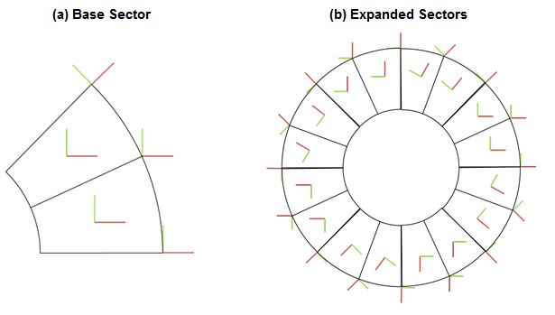
Results are displayed or printed in the currently active results coordinate system (RSYS). For RSYS,SOLU, the result is in the nodal coordinate system of the base sector, and it is rotated to the expanded sector’s location, as demonstrated in Figure 3.2: Cyclic Results Coordinate Systems with RSYS,SOLU.
Care must be taken when interpreting RSYS,SOLU (especially averaged nodal stress and strain) results when the solution coordinate systems are not in the cyclic cylindrical system. Using RSYS,SOLU can be useful when you want to track sliding motion along a contact interface or a stress in a single crystal alloy. Note that /POST26 only works in the RSYS,SOLU system.