Cyclic symmetry modal analyses currently support the Block
Lanczos, PCG Lanczos, Supernode, Subspace, Unsymmetric, Damped, and QR Damped methods
(MODOPT command). The Supernode eigensolver is not recommended as
the solutions for multiple frequencies (pairs) may be inaccurate. For the Unsymmetric
method, complex eigensolutions are not supported. For the Damped and QR Damped methods,
only unit normalization is supported (MODOPT with
Nrmkey = ON).
This section describes harmonic indices in relation to modal cyclic symmetry analyses and provides information necessary for solving several types of modal analyses:
- 4.1.1. Understanding Harmonic Index and Nodal Diameter
- 4.1.2. Stress-Free Modal Analysis
- 4.1.3. Prestressed Modal Cyclic Symmetry Analysis
- 4.1.4. Large-Deflection Prestressed Modal Cyclic Symmetry Analysis
- 4.1.5. Unsymmetric Modal Solution for Fluid-Structure Interaction
- 4.1.6. Damped and QR Damped Modal Solution
- 4.1.7. Postprocessing a Modal Cyclic Symmetry Analysis
To understand the process involved in a modal cyclic symmetry analysis, it is necessary to understand the concepts of harmonic indices and nodal diameters.
The nodal diameter refers to the appearance of a simple geometry (for example, a disk) vibrating in a certain mode. Most mode shapes contain lines of zero out-of-plane displacement which cross the entire disk, as shown in these examples:
For a complicated structure exhibiting cyclic symmetry (for example, a turbine wheel), lines of zero displacement may not be observable in a mode shape.
The harmonic index is an integer that
determines the variation in the value of a single DOF at points spaced at a
circumferential angle equal to the sector angle. For a harmonic index equal to nodal
diameter , the function
describes the variation. This definition allows a varying number
of waves to exist around the circumference for a given harmonic index, provided that
the DOF at points separated by the sector angle vary by
. For example, a harmonic index of 0 and a 60° sector produce
modes with 0, 6, 12, ... , 6
waves around the circumference.
The nodal diameter is the same as the harmonic index in only some cases. The solution of a given harmonic index may contain modes of more than one nodal diameter.
The following equation represents the relationship between the harmonic index
and nodal diameter
for a model consisting of
sectors:
(4–1) |
| where |
For example, if a model has seven sectors ( = 7) and the specified harmonic index
= 2, the program solves for nodal diameters 2, 5, 9, 12, 16, 19,
23, ....
The following table illustrates Equation 4–1, showing how the harmonic index, nodal diameter and number of sectors relate to one another:
| Harmonic Index (k) | Nodal Diameter (d) | |||||
|---|---|---|---|---|---|---|
| 0 | 0 | N | N | 2N | 2N | ... |
| 1 | 1 | N-1 | N + 1 | 2N - 1 | 2N + 1 | ... |
| 2 | 2 | N - 2 | N + 2 | 2N - 2 | 2N + 2 | ... |
| 3 | 3 | N - 3 | N + 3 | 2N - 3 | 2N + 3 | ... |
| 4 | 4 | N - 4 | N + 4 | 2N - 4 | 2N + 4 | ... |
| ... | ... | ... | ... | ... | ... | ... |
|
N / 2 (N is even) | N / 2 | N / 2 | 3N / 2 | 3N / 2 | 5N / 2 | ... |
| (N - 1) / 2
(N is odd) | (N - 1) / 2 | (N + 1) / 2 | (3N - 1) / 2 | (3N + 1) / 2 | (5N - 1) / 2 | ... |
Note: To avoid confusion, be aware that in some references mode refers to harmonic index as defined here and nodal diameter describes the actual number of observable waves around the structure.
Harmonic Index in an Electromagnetic Analysis — For electromagnetic analyses, only the EVEN and ODD harmonic index settings (see the CYCOPT command) are valid (for symmetric and antisymmetric solutions, respectively).
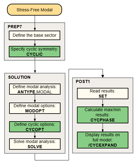
The following flowchart illustrates the process involved in a stress-free modal cyclic symmetry analysis.
A modal cyclic symmetry analysis allows only cyclically symmetric applied boundary conditions. Eigensolutions are performed, looping on the number of harmonic indices specified (via the CYCOPT command) at each load step.
The number of modes specified on the MXPAND command is equal to the number of modes extracted per harmonic index.
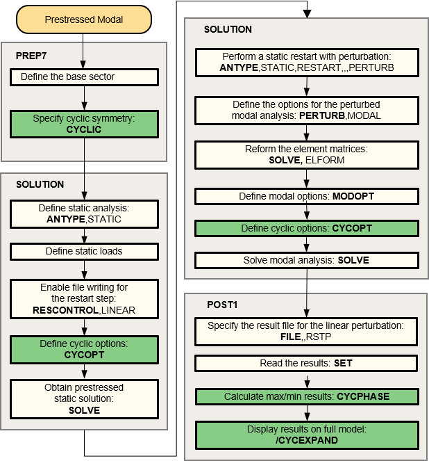
The process for a prestressed modal cyclic symmetry analysis is essentially the same as that for a stress-free case, except that a static solution is necessary to calculate the prestress in the base sector. The prestress state of the sector may be from a linear static or a large-deflection nonlinear static analysis. The following flowchart illustrates the process involved in a prestressed modal cyclic symmetry analysis.
The modal cyclic symmetry solution occurs after the static cyclic symmetry solution. The modal solution uses the same low- and high-edge components defined in the static cyclic analysis stage (via the CYCLIC command). The analysis yields the eigenvectors of the structure in the prestressed state.
Geometric nonlinearity occurs when the deflections are large enough to cause significant changes in the geometry of the structure. In such cases, the equations of equilibrium must account for the deformed configuration. When a nonlinearity is present, the program uses an iterative process to obtain the solution.
To calculate the frequencies and mode shapes of a deformed structure, you can perform a prestressed modal analysis (using the linear perturbation solution method) of cyclic structures after first performing a large-deflection (NLGEOM,ON) static analysis. Other nonlinearities such as frictional contact may also be included.
The prestress effects are automatically accounted for in the linear perturbation modal analysis procedure.
To obtain the cyclic symmetry modal solutions of a deformed structure, follow these steps:
Perform a nonlinear static solution with the prestress load. Use the RESCONTROL command to define the necessary restart files. Non-cyclically symmetric loading cannot be applied.
Restart the previous static solution from the desired load step and substep.
Issue the PERTURB command to define the analysis type, material behavior to be used, contact status (
ContKey= CURRENT, STICKING, or BONDED) and load values to be retained from the previous static solution (LoadControl= ALLKEEP, INERKEEP, PARKEEP, DZEROKEEP, or NOKEEP).Modify the behavior of individual contact pairs, as needed, using the CNKMOD command.
Issue the SOLVE,ELFORM command to regenerate the matrices.
Issue the MODOPT and MXPAND commands to specify the modal analysis option.
Issue the SOLVE command to perform the eigensolution.
Postprocess the results from the Jobname.rstp file.
Note: During the SOLVE,ELFORM (Step 5), the coordinates of the model are updated to account for the large deflections of the static analysis. Any subsequent nodal coordinate listings and geometry plots will be in this updated state.
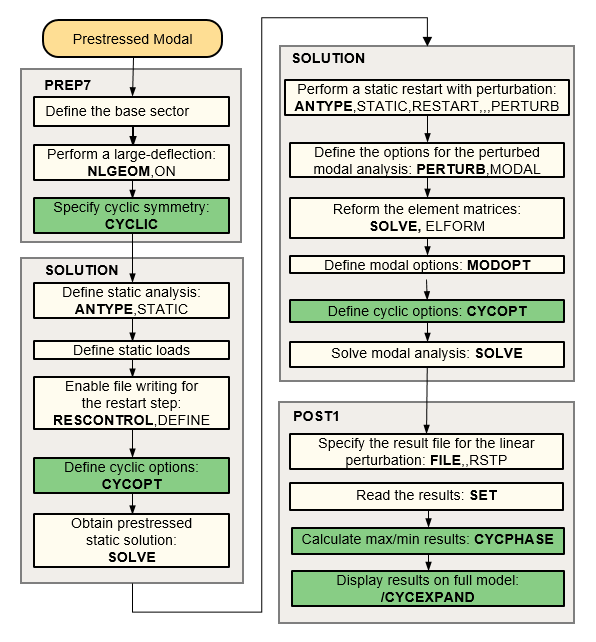
The flowchart below illustrates the process involved in a large-deflection prestressed modal cyclic symmetry analysis.
For detailed information about the linear perturbation analysis procedure, see Linear Perturbation Analysis in the Structural Analysis Guide. In addition, Example 9.4: Contact Status Control in a Linear Perturbation Modal Analysis in that same document provides a complete example input listing for a linear perturbation cyclic symmetry modal analysis.
The unsymmetric modal eigensolver can be used for a subset of cyclic symmetry solutions related to fluid-structure interaction (FSI). This solution is activated when structural and acoustic elements are present in a cyclic symmetry model, and the command MODOPT,UNSYM is specified.
The unsymmetric eigensolver is intended for FSI problems that do not have complex eigensolutions. Only real-valued eigensolutions can be obtained from a cyclic unsymmetric modal solution.
In this type of analysis, both the base and duplicate sectors need to be stored.
Therefore, CYCOPT,MSUP,0 is the default for cyclic FSI
problems. These modes cannot be used as a basis for
cyclic mode-superposition harmonic analyses (CYCOPT,MSUP,1).
Also, note that issuing MODOPT with
ModType = BOTH creates files only for the last
harmonic index solution in the cyclic modal analysis.
Refer to Using Cyclic Symmetry with Fluid-Structure Interaction in the Acoustic Analysis Guide for more details, including a list of supported element types and an example.
The damped and QR damped algorithms (DAMP and QRDAMP on MODOPT) can be used to compute damped modal results for any type of damping (excluding modal damping) as well as account for Coriolis effects (CORIOLIS). Complex eigenvalues and the corresponding unit normalized mode shapes can be obtained.
In these analysis types, both the base and duplicate sectors need to be stored. Therefore, CYCOPT,MSUP,0 is the default for cyclic damped and cyclic QR damped problems.
For a QR damped analysis with cyclic symmetry, the reuse of the eigensolution from
a previous load step (QRDOPT,ReuseKey)
is not supported.
Creation of Campbell diagrams with cyclic damped modal analysis is not supported.
When postprocessing results of a modal analysis using the damped eigensolver (MODOPT, DAMP), use the MAXCYCMODE command to compute the amplitude of a single complex mode.
See Example Damped Modal Cyclic Symmetry Analysis for a detailed example.
Cyclically symmetric geometries in a modal analysis may generate mode pairs having the same frequency, which leads to an inherent indeterminacy. Modes may exhibit a different phase angle at each solve and may be different compared to the equivalent full 360° model. However, the combination of the two modes is unique and can be used to compare solutions. Use the MAXCYCMODE command to compute the maximum value of displacement or stress of cyclic mode pairs in separate modal analysis solutions and evaluate equivalency. For details, see Comparison using the MAXCYCMODE command
In the solution output, the participation factors and modal mass are listed. The
participation factors are only valid for harmonic index 0 (and only for UZ and ROTZ
in the cyclic coordinate system) and for harmonic index 1 (and only for UX, UY,
ROTX, and ROTY in the cyclic coordinate system). They are multiplied by
for harmonic index 0 and
for harmonic index 1 so that they match the participation factors
from a full 360° model. If CYCOPT,MSUP,NO is specified,
participation factors for other harmonic indices will be computed, but may not have
a relationship to the full 360° model. The modal mass is
(or N if the harmonic index is 0 or
). If the modes have been normalized to unity
(
Nrmkey on MODOPT), then the
participation factors and modal mass will also be scaled based on that mode's
normalization factor. The *GET,,,PFACT command can only be used
to get the participation factor if CYCOPT,MSUP,NO is
specified.
Note: Because the modal effective mass calculation does not consider constraint equations, the modal effective masses of a cyclic symmetry model do not match the equivalent full 360° model for harmonic indices greater than zero.
A cyclic symmetry solution typically has multiple load step results depending upon the harmonic index solutions requested. The SET,LIST command will list the harmonic indices solved and the frequencies within each harmonic index. Use SET,LIST,,,,,,,ORDER to list the frequencies themselves in numerical order.
To transform the real and imaginary cyclic symmetry solution results to the actual structure solution, three postprocessing (/POST1) commands are available:
Note: The CYCPHASE command uses full model graphics (/GRAPHICS,FULL) to compute peak values. Because of this, there may be slight differences between max/min values obtained with CYCPHASE, and those obtained via /CYCEXPAND (/GRAPHICS,POWER).
For information about /CYCEXPAND and EXPAND command usage, see Expanding the Cyclic Symmetry Solution. For information about CYCPHASE command usage, see Phase Sweep of Repeated Eigenvector Shapes.
This section describes the capabilities of the /CYCEXPAND and EXPAND commands and explains their differences. Use the commands to expand the solution results of your cyclic symmetry analysis to the full model.
The /CYCEXPAND command does not modify the geometry, nodal displacements, or element stresses stored in the database. The /CYCEXPAND command uses the following equation to perform the expansion:
(4–2) |
where
|
|
|
|
|
|
|
|
|
|
For more details, see Using the /CYCEXPAND Command.
The EXPAND command offers an alternate method for displaying the results of a modal cyclic symmetry analysis. It is a specification command that causes a SET operation to transform and expand the data it is reading before storing it in the database. If you request two or more sector repetitions, the command creates additional nodes and elements to provide space for the extra results. After the expanded results are stored in the database, you can plot (PLESOL or PLNSOL), print (PRNSOL). You can also process them as you would those for a non-cyclic symmetry analysis, in cases where you may wish to process results in a manner unsupported by the /CYCEXPAND command. Care should be taken in such cases as the database can become very large, negating the inherent model size advantage of a cyclic symmetry analysis.
The EXPAND command supports the post-processing of strain energies for brick and tetrahedral models. Kinetic energies are not supported.
For the equations used to normalize the mode shapes, refer to Complete Mode Shape Derivation in the Theory Reference.
When mode shapes are normalized using the maximum value of the mode, it is possible that the true maximum value does not correspond to the maximum value of the actual instance of the mode computed. This is because the mode pairs at a single eigenvalue can be clocked at a random phase angle, which may lead to a norm of slightly less than one.
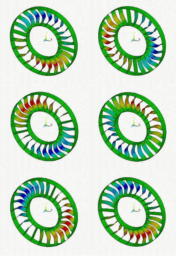
After you have completed a modal cyclic symmetry analysis, you can apply an animated traveling wave to the cyclic model by issuing the ANCYC command (which uses /CYCEXPAND functionality). The traveling wave capability applies only to modal cyclic symmetry analyses. For more information, see the description of the ANCYC command in the Command Reference.
Figure 4.5: Traveling Wave Animation Example illustrates the ANCYC command's effect. To view the input file used to create the model shown, see Example Modal Cyclic Symmetry Analysis.
The following demo is presented as an animated GIF. View online if you are reading the PDF version of the help. Interface names and other components shown in the demo may differ from those in the released product.
In a modal cyclic
symmetry analysis, repeated eigenfrequencies are obtained at
solutions corresponding to harmonic indices, k, that are not equal to 0 or N/2.
The repeated modes are a consequence of the cyclically symmetric geometry of the
structure or assembly being modeled by the cyclic sector.
The eigenvector shapes corresponding to the repeated eigenfrequencies are not unique. That is, for the repeated eigenfrequencies fi = fi+1, the mode shapes corresponding to fi and fi+1 can be linearly combined to obtain a valid mode shape solution for the frequencies fi and fi+1. The linear combination can be written as:
(4–3) |
where,
|
|
|
|
The orientation of the combined mode shape,
, will be along nodal diameter lines which are different from
those of
and
. Because the full structure may have stress-raising features
(such as bolt holes), determining the eigenvector orientation that causes the
most severe stresses, strains, or displacements on the structure or assembly is
critical.
To determine the peak values of stresses, strains or displacements in the full
structure or assembly, it is necessary to calculate at all possible angular orientations ϕ in the range of 0
through 360°. The CYCPHASE command performs this
computational task.
Because and
are arbitrary constants, the CYCPHASE
calculation rewrites Equation 4–3 as follows:
(4–4) |
Note that the CYCPHASE computation returns results only for
the first sector ( is reduced to the first sector displacements).
Using the cyclic symmetry expansion of Equation 3–2 in Equation 4–4, the simplified phase-sweep equation that operates on the cyclic sector solution (rather on the computation-intensive full-structure expression in Equation 4–4) is:
(4–5) |
where indicates the first sector.
A phase sweep using the CYCPHASE command provides information about the peak values of stress, strain, and/or displacement components and the corresponding phase angle values. You can then expand the mode shape at that particular phase angle to construct the eigenvector shape that produces the peak stress, strain, and/or displacement.
Example:
To determine the eigenvector orientation that causes the highest equivalent stress, perform a phase sweep on the stress via the CYCPHASE,STRESS command. Obtain a summary of the phase sweep via the CYCPHASE,STAT command to determine the value of ϕ at which maximum equivalent stress occurred. You can shift the mode shape to that angle via the /CYCEXPAND,,PHASEANG command and plot the expanded mode shape via the PLNSOL,S,EQV command.
Note: The CYCPHASE command uses full model graphics (/GRAPHICS,FULL) to compute peak values. Because of this, there may be slight differences between max/min values obtained with CYCPHASE, and those obtained via /CYCEXPAND (/GRAPHICS,POWER).
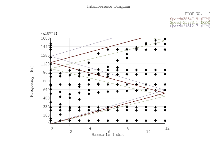
The interference diagram, generated using the PLZZ command, plots the cyclic modal frequencies versus the harmonic index (or nodal diameter). If the rotational speed is provided (or known from a prior prestressing step using linear perturbation, see Prestressed Modal Cyclic Symmetry Analysis), the speed line is superimposed on the diagram. This is also known as a SAFE diagram or a ZZENF diagram [1], and indicates potential frequencies where resonance may occur.
Figure 4.6: Interference Diagram illustrates an interference diagram with the speed line and two additional speed lines enveloping the primary speed line.


