
The Edit Layers Window
A stackup is a list of physical layers in a circuit board. It can be laminated, overlapping, or multizone. The layers of a stackup are configured in the Edit Layers window which contains information about both the stackup layers and the non-stackup (i.e., non-physical) layers. The Edit Layers window describes the type, properties, visibility, attributes and analysis of each layer.

To open the Edit Layers window, do one of the following from the Layout tab.
-
From the Layout ribbon, select
 Layers dialog.
-
From the Layout or Footprint menu, select Layers .
-
Right-click in the Layout Editor and select Edit Layers.
The Edit Layers window is divided into the following group boxes.
-
Display – choose which layers appear in the table (e.g., Stackup layers, Non-stackup layers, or All layers).
-
Stackup – select the Type (e.g., Laminate, Overlapping, Multizone [Beta]) and Units (e.g., centimeters, millimeters, meters, etcera) displayed in the Grid Control Table.
-
Grid Control Table – view type, properties, visibility, attributes and analysis of each layer
-
Layer – Insert a new layer above or below, remove a layer, or select either all the Remove, pane adds, removes, and selects types of layers.
-
Edit selected – After selecting a layer in the Grid Control Table, edit the layer's Name, Type, Material, Thickness, and Top bottom attributes.
-
Visibility – After selecting a layer in the Grid Control Table, edit the layer's Name, Type, Material, Thickness, and Top bottom attributes.
-
Attributes – After selecting a layer in the Grid Control Table, edit the layer's Name, Type, Material, Thickness, and Top bottom attributes.
-
Analysis – After selecting a layer in the Grid Control Table, edit the layer's Name, Type, Material, Thickness, and Top bottom attributes.
-
TSV – Activate and deactivate TSV layers.
If the TSV area does not appear, ensure a via layer is selected or reselected in the Grid Control Table. To create a via layer, refer to Via Layers.
-
Stackup Viewer – Displays a diagram of the layers.
When the Edit Layers window opens, it displays the current type of stackup and its most recent display options.
All of the Edit Layers window’s functionality appears on its Primary tab, unless the stackup is multizone. A multizone stackup has a tab for each zone with its controls are spread across the tabs.
From this window, you can import a stackup from an XML file and export an existing stackup to an XML file. Also use the Layer Stackup Wizard.
Stackup Type
AEDT offers three types of stackups in the Type drop-down menu:
- Laminate: all layers physically stack one another with no overlap on the Z-axis. This is the default type.
- Multizone: layers physically stack on one another in the Z-axis but each layer can have zones made of different or no material.
- Overlapping: layers can physically intersect one another in the Z-axis.
The Edit Layers window offers different controls bases on what the type of stackup. It is generally possible to switch between stackup types. When that cannot happen, the Type drop-down menu becomes unavailable.
Display Options and Units
The Edit Layers window can display Stackup layers, Non-stackup layers, or All layers in the Grid Control pane.
All measurements in this window use the same units. These units are set in the Units drop-down menu in the Stackup pane. The default is millimeters. Your choice of Units affects the physical layers’ thickness and elevations.
Grid Control Pane
The Grid Control displays the physical and non-physical layers, as determined by the Display radio buttons. Layers are color coded:
- Blue: highlighted
- Gray: locked
- Green, light: dielectric layer
- Green, dark: active dielectric layer
- Pink: divider between physical and non-physical layers
- White: signal or non-physical layer
- Yellow: active signal or non-physical layer
A variety of columns allow users to see and edit information about each layer. What can be seen and edited varies by type of layer and stackup. Some columns are hidden by default. Right-click the column labels of the Grid Control pane to see a complete list of columns. If a column does not apply to a layer, it is blank in that layer’s row. Thus many columns are empty for non-physical layers.
The Grid Control pane’s shortcut menu provides actions for the selected layers. A new layer can be inserted, or the selected layer can be activated. A layer can be locked in place or assigned to a specific zone in a multizone stackup. If multiple dielectric layers are selected, they can be merged.
Grid Control Columns
- Row Color/Type Icon: This matches what is shown for the layer in the Layout Editor. Clicking this cell to select the row.
- Wireframe: Check box to set drawing on the layer as wireframe outlines or solid.
- Visibility settings: Controls what is visible on each layer. The visibility settings determine what types of objects are shown on a layer. Similar settings are in the Layers window.
- Visibility - Sets visibility for all objects on the layer
- Shape visibility - Sets visibility for shapes on the layer
- Line visibility - Sets visibility for lines on the layer
- Pad visibility - Sets visibility for padstack pads on the layer
- Hole visibility - Sets visibility for padstack holes on the layer
- Component visibility - Sets visibility for components and black boxes placed on the layer
- Name: Editable name of the layer
- Type: Editable type of the layer. Choices are given in a drop-down menu that varies for stackup and non stackup layers. Ground is no longer a layer type choice. To create what was previously described as a ground or metalized signal layer, set the type to signal and the Negative state on.
- Negative: Type of geometry to be drawn on the layer. Geometry on a negative layer cuts away on the layer. Geometry on a positive layer adds to it. This setting is used in conjunction with the signal type to create a layer used as a ground layer. This column is visible if the stackup contains a layer set to negative. Hidden by default.
- Material: Editable choice of material for the layer. The drop-down menu contains names of materials already in the project that are allowed for the given type of layer. The first choice in the menu is Edit, which allows users to open the Materials tab of the Select Definition window. Users can type in a project variable that is a text array reference. This allows parameterization of the material (e.g., there is a project array variable $mat that is defined to have the strings "copper" and "Cu_Pkg" and there is a project array $i that is defined to be 1. The user may set the material for a layer to be $mat[$i]. The material used are copper.).
- Dielectric Fill - specifies the material to use to fill in around geometry on the layer. The dielectric material can be chosen in the same way that layer material is chosen. Hidden by default and not available for overlapping stackups.
- Dielectric Constant - Hidden by default.
- Loss Tangent - Hidden by default.
- Thickness: Editable thickness of the layer. It can contain variables or expressions.
- Evaluated Thickness: the calculated value of the thickness. Hidden by default.
- Top Bottom Association: Allows users to set top bottom association for the layer. Hidden by default.
- Etch: Allows etching on signal layers.
- Rough: Allows roughness on signal layers.
- Solver: Enables the use of specified solver options. Solver options are available for signal and dielectric layers.
- Lower: In an overlapping stackup, the lower elevation of signal layers can be user-defined with a number, variable, or expression. The lower elevation of dielectrics is displayed, but not editable.
- Upper: Contains of the upper elevation of the layer based on the lower elevation and the thickness of the layer. It is not editable.
- Lower elevation: The calculated value of the lower elevation. This is useful if the Lower value contains a variable or expression.
- Upper elevation: The calculated value of the upper elevation. This is useful if the Lower value contains a variable or expression.
- Pattern: Fill pattern used on the layer. Hidden by default.
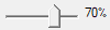
- Transparency: Transparency values lie between 0 (completely opaque) and 100 (completely transparent). Values may be entered directly into the column or using the Attributes slider bar. The slider bar may be used to adjust the transparency for multiple layers. Select multiple rows either directly or through the selection pull-down.
Layer Pane
From the Layer pane, you can insert a layer, remove layers, and select layers based on their type. These operations can affect multiple layers simultaneously.
Edit Selected Pane
The Edit Selected pane offers controls that can edit multiple layers simultaneously. Select the layers in the Grid Control pane or Layers pane first. Controls are only available for the layers to which they apply. A control duplicated by a Grid Control column is always visible, even if its column is hidden. The controls are:
|
Control |
Also available in |
Icon or Control |
| Name | Grid Control column | |
| Type | Grid Control column | |
| Material | Grid Control column | |
| Thickness | Grid Control column | |
| Top bottom | Grid Control column | |
| Visibility controls | Grid Control column and Layers window | |
| Layer color |
 (color may vary) (color may vary) |
|
| Negative | Grid Control column | |
| Wireframe | Grid Control column |

|
| Transparency | Grid Control column |
|
| Locked | Grid Control shortcut menu |

|
| Etch | Grid Control column | |
| Rough | Grid Control column | |
| Solver | Grid Control column |
HFSS geometry allows for the presence of an etch factor in the design and modeling of different substrate layers. Check the Etch check box to use an etch factor when the mesh is created and check the Etch check box to set the etch factor.
By default, layers do not have roughness. To add surface roughness a layer, check its Rough column check box. The roughness is added to the layer when its mesh is created. For more information, see Setting the Layer Surface Roughness.
Signal layers may have solver options including Solve Inside Solver. Click the Solver check box in the Analysis pane to activate the solver options and the Solver button to open the Solver Options window.
Stackup Viewer
The Stackup Viewer is a 2D diagram that displays stackup layers. A column of dielectric layers is on the left with columns of signal and via layers on the right. Via layers are thinner than signal layers. The Stackup Viewer can be customized for useability, to show elevation lines separating signal and dielectric layers, to display only visible layers, and show or hide tool tips and layer names.
Each stratum has a name and color that corresponds to a layer in the Grid Control. Click on a stratum to select its layer in the grid. To show or hide layer names, right-click Stackup Viewer and click Layer Names. If layers in the stackup are hidden, they can be shown or hidden in the Stackup Viewer. Right-click the Stackup Viewer and click Show Only Visible Layers.
Strata are divided by elevation lines. The elevation lines for signal layers are dotted and for dielectric layers are solid. These lines may overlap depending on the type of stackup displayed. To show or hide the elevation lines, right-click Stackup Viewer, click Elevation Lines, then select the type of line.
The Stackup Viewer can be normalized for usability. Normalizing spaces dielectric layers evenly and normalizes the spacing of signal layers relative to the dielectric layers they overlap with. The normalized view emphasizes how the layers stack on one another, instead of the layers' relative size. Remove the normalization to view the layers in their proportional sizes. To use or deactivate normalization, right-click Stackup Viewer and click Normalize. You can zoom in on the diagram by using your mouse. To reset the zoom, right-click Stackup Viewer and click Reset Zoom.
When tool tips are activated, you can hover over a stratum to see its name, relative permittivity, relative permeability, and/or conductivity. To deactivate or activate tool tips, right-click Stackup Viewer and click Tooltips. The tool tips only appear if this option is active.
To save an image of the Stackup Viewer, right-click Stackup Viewer and click Copy Image. The image is copied to your computer’s clipboard.