
Setting the Layer Surface Roughness
The surface roughness model is used to compute conduction losses for surfaces. Surface roughness increases conduction losses, such as the interface between the conductor and the substrate for a microstrip line. The Surface Roughness Model window is accessed through the Edit Layers window. To access the Surface Roughness window:
- Check the Rough area for a selected layer in the Edit Layers window.
- Click Roughness to open the Surface Roughness Model window.
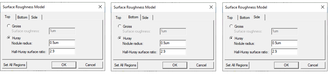
The surface roughness of top and bottom layers is set independently. Also set one roughness for the sides. There is a separate tab in the window for each.
- Select either the Top, Bottom, or Side tab.
- Select either Groiss or Huray:
- For the Groiss model, specify a Surface roughness parameter as a value/variable, then specify the corresponding units. The Groiss model is a traditional-case model. It is not causal and is only suitable for frequency-domain computations. It is also limited to a maximum impedance multiplying factor of 2, which corresponds to highly polished conductor surfaces. Legacy projects use the Groiss model by default.
- For the Huray model, also specify the Nodule radius value, which is the radius of copper spheres used to model the surface roughness. Next, specify the Hall-Huray surface ratio, which is a unitless quantity. The Huray model is causal.
- The surface roughness of each surface is set independently. To copy the settings from one surface to the other two:
- Set the chosen model for one of the surfaces.
- Click Set All Regions.
- Click OK.