


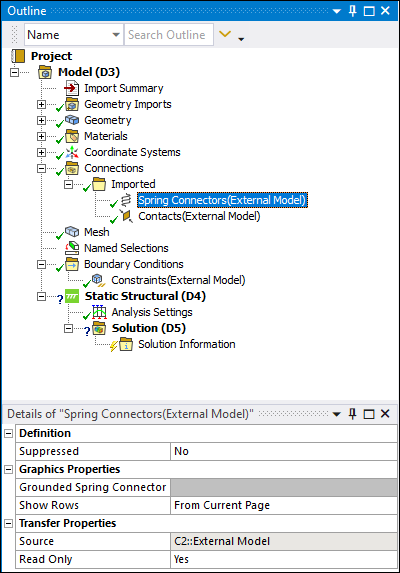
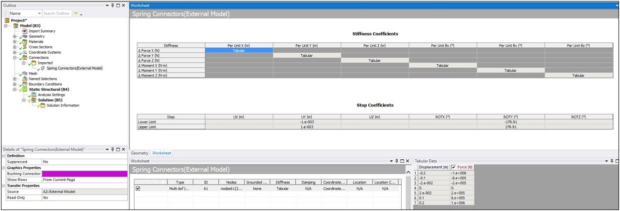
When your upstream External Model source file includes spring connections and bushings, an Imported folder appears beneath the Connections parent folder when you open the file in Mechanical. This object is a simple group folder. It contains the child objects: Spring Connectors. The data associated with the imported springs and bushing is provided through the Worksheet. Worksheet content, including default settings, is based on the data in the external file.
Spring Example
Bushing Example
Nonlinear Bushing Example
Supported Analysis Types
Imported Spring Connectors are supported by the following analysis types:
Coupled Field Analyses
Harmonic Response
Modal
Static Structural
Transient Structural
Supported Source File Commands
The application imports the following source file data/commands as springs:
- CDB
For the CDB file type imported into Mechanical through External Model, the application only processes:
COMBIN14 linear spring elements with the following restrictions:
For the supported constants of this element type, Mechanical only processes Real Constants Stiffness (K) and structural Damping Coefficient (CV1). If your input data includes any real constant in addition to K or CV1 (such as CV2), these additional values are not processed.
Mechanical does not process material commands.
Supported KEYOPT,2 numbers include structural degrees of freedom only.
COMBIN39 nonlinear spring elements with the following restrictions:
Supported KEYOPT,3 numbers include translational degrees of freedom only.
Mechanical does not process material commands.
- NASTRAN
Mechanical supports the processing the CELAS1, CELAS2, CBUSH, and PBUSH commands only from a NASTRAN file with the following requirements:
Mechanical only processes stiffness(K) and structural damping (GE). The stress coefficient is not processed.
If GB (grid point B) is blank, the application assumes that the next node is grounded and creates a new node with the same location as the previous node.
For CELAS1 and CELAS2 commands the first DOF will be taken as the operating DOF for the spring.
For the PBUSH command, Mechanical supports the stiffness coefficients K1, K2, K3, K4, K5, K6 and structural damping coefficients (GE1, GE2, ... GE6).
- ABAQUS
Spring Connections
For spring data imported from ABAQUS, Mechanical processes the element types:
SPRING1 (spring element between a node and ground acting in a fixed direction).
SPRING2 (spring element between two nodes acting in a fixed direction). For this element type, the application will import nonlinear force-displacement spring data that contains the origin, if the NONLINEAR parameter is used with the *SPRING keyword.
SPRINGA (spring element between two nodes with its line of action being the line joining the two nodes).
In addition, the application supports the following *SPRING options, however, all other fields are ignored:
Orientation via Imported Nodal Orientation.
Degree of freedom, stiffness and structural damping coefficients.
Linear and nonlinear behavior.
Important: For SPRING1 elements, an additional node is created in the same spot as the given node and that node is grounded when sent to the solver.
Bushing Connections
Mechanical supports the following ABAQUS bushing keywords:
*ELEMENT: This keyword requires the TYPE parameter CONN3D2 as well as the Data Lines that include the Element IDs and two node IDs (two nodes must be present). You can also use the optional parameter ELSET. Note that the ELSET Name must match name the *CONNECTOR SECTION keyword. Grounded bushings are not supported.
*ELSET: This keyword requires the ELSET parameter whose name must be included on either the *ELEMENT or *ELSET keywords as well as the name of the *CONNECTOR SECTION keyword.
*ORIENTATION: This keyword requires the NAME Parameter and this parameter must match the name given on the second line of the *CONNECTOR SECTION keyword.
*CONNECTOR SECTION: This keyword requires the ELSET and BEHAVIOR parameters whose names must be included on either the *ELEMENT or *ELSET keywords or the *CONNECTOR BEHAVIOR keyword. In addition, the first Data Line must define BUSHING as the type of connector and the second line must define the name of the coordinate system and must match a name on the *ORIENTATION keyword. Only the first Orientation name is used.
*CONNECTOR BEHAVIOR: This keyword requires the NAME Parameter. This Parameter must also match name used with the BEHAVIOR parameter on the *CONNECTOR SECTION keyword. In addition, the *CONNECTOR BEHAVIOR keyword must be immediately followed by the keywords *CONNECTOR ELASTICITY and *CONNECTOR STOP (as described below).
*CONNECTOR ELASTICITY: This keyword may be repeated up to six times for the values of a DOF. It requires the COMPONENT Parameter and the COMPONENT Parameter must represent a DOF direction. Directions values include: 1 = UX, 2 = UY, 3 = UZ, 4 = ROTX, 5 = ROTY, 6 = ROTZ
The NONLINEAR Parameter is optional unless your input includes a table of Stiffness vs Constraint, in which case it is required.
The solution does not allow both nonlinear and linear data. Linear data is ignored during the solution. To ensure proper nonlinear effects, set the Large Deflection property to .
Corresponding Data Lines include, if Nonlinear, Stiffness and Constraint. And, the line is repeated for each Stiffness, Constraint pair in a table. If the Data Line is Linear, it includes Stiffness.
*CONNECTOR STOP: This keyword requires the COMPONENT Parameter and a data line that includes an Upper limit and a Lower limit value.
Also see the Imported: Spring Connectors object reference section.