The Geometric Modification category provides the features described below. As described, this category only displays when certain contact conditions are detected by the application and/or certain property definitions are specified.
Interface Treatment
The Interface Treatment property defines how the contact interface of a contact pair is treated. The property becomes visible when you set the contact Type property to either , or (nonlinear contact). For a given contact interface (Contact Region) that includes either gaps or penetrations, either locally or uniformly along the overall surface, contact adjustments, such as closing the gaps, removing the penetrations, or shifting the contact surface by an Offset may produce a better setup for initial contact.
To see the initial contact, you can insert a Contact Tool under the Connections folder. An Initial Information object is automatically inserted under the Contact Tool. Using the context (right-click) menu this object, select the option. This option produces a table of information for all Contact Regions. The Status column indicates the contact interface as Near Open, Closed, or Far Open. Using this information, your selection for the Interface Treatment property can improve the contact status from or to . Having a in status at the beginning of the analysis may improve the convergence of the model.
When active, the Interface Treatment property provides the options illustrated here. Each option is described below.
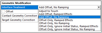
: Any initial gaps are closed and any initial penetration is ignored creating an initial stress free state. Contact pairs are "just touching" as illustrated.
Contact pair before any Interface Treatment. Gap exists. Contact pair after Adjust to Touch treatment. Gap is closed automatically. Pair is "just touching". 
Contact pair before any Interface Treatment. Penetration exists. Contact pair after Adjust to Touch treatment. Pair touches at interface. This setting is useful to make sure initial contact occurs even if any gaps are present (as long as they are within the pinball region). Without using this setting, the bodies may fly apart if any initial gaps exist. Although any initial gaps are ignored, gaps can still form during loading for the nonlinear contact types. For nonlinear contact types (Frictionless, Rough, and Frictional), Interface Treatment is displayed where the choices are , , , and , .
Note:The option does not lead to uniform contact between concentric cylinders that contain a small initial gap. For this situation, manually specify the gap as an offset in with the option.
Gaps may still be present if the contact pair has regions of differing gaps. When gaps exist, this setting makes sure that initial contact occurs by closing the smallest gap.
: Models the true contact gap/penetration plus adds in any user defined offset values. This setting is the closest to the default contact setting used in the Mechanical APDL except that the loading is ramped. Using this setting will not close gaps. Even a slight gap may cause bodies to fly apart. Should this occur, use a small contact offset to bring the bodies into initial contact. Note that this setting is displayed only for nonlinear contact and the ramping occurs over the first load step.
: This is the default setting. This option is the same as Add Offset, Ramped Effects but loading is not ramped.
: Using this option, the application ignores any initial geometric penetrations if the initial status is in contact. If the initial status is near field, the application ignores the calculated initial penetration ( plus geometric gap), and applies only the remaining value (remaining from plus geometric gap calculation). All loading for this option is ramped.
: This option performs the same actions as the options except that loading is step-applied.
: This option is the same as the option except that this option ignores any initial geometric penetration or gap when calculating contact regardless of the initial contact status, before applying a uniform offset.
: This option performs the same actions as the options except that loading is step-applied.
Offset: This property displays for all of the options of the Interface Treatment property except . This property defines the contact offset value. A positive value moves the contacts closer together (increase penetration/reduce gap) and a negative value moves the contacts further apart.
Contact pair before any Interface Treatment. Gap exists. Contact pair after Add Offset treatment (either option). Gap is closed "manually" based on value entered for Offset (positive value shown that includes some penetration).
Contact/Target Geometry Correction
The Contact Geometry Correction and the Target Geometry Correction properties both have the default setting as well as the following two options for geometry correction.
Smoothing
For Contact and/or Target geometries, the Smoothing option enables you to improve the accuracy of circular edges (2D) and spherical or revolute surfaces (3D) by evaluating the contact detection based on the exact geometry instead of the mesh. This feature enables curved geometries to be analyzed more effectively using meshes with dropped midside nodes. For additional technical information about this feature, see the Surface Smoothing section of the Mechanical APDL Contact Technology Guide.
Note:
The Behavior properties and are not supported.
To avoid having the application incorrectly modify the geometry of a contact surface that has drastically deformed, do not use the Smoothing feature during an analysis that has specified Large Deflection.
The following properties become visible when the Contact Geometry Correction property and/or the Target Geometry Correction property are set to .
- Orientation
Property options include:
- Program Controlled
When contact scoping is a sphere, the option is invalid if the scoping includes more than one spherical scoping.
When contact scoping is a cylinder, the option:
Is invalid if the CAD package does not identify it as a cylinder. In this case, you can confirm your model's geometric information using the Selection Information window.
Supports any number of cylindrical scoping if 1) all cylindrical radii are equal, and 2) all cylindrical axes are colinear.
Note: A default tolerance for the equality is set to
1e-6or0.0001%. You can adjust the tolerance using the variablecylindrical smoothing tolerance. See the Settings Variables section for more information.If the option is not valid, you can use the option to manually identify the cylinder.
Note: The option for cylindrical smoothing sends the cylinder’s basepoint from the CAD package as the cylinder endpoints in the SECDATA command. See the Geometry Correction for Contact and Target Surfaces section in the Mechanical APDL Contact Technology Guide for more information.
- Sphere Center Point
(3D) or (2D): When one of these properties is selected, the Center Point property also displays. The Center Point property provides a drop-down list of available coordinate systems, Global as well as user-defined. As needed, create a local coordinate system at the center of your sphere.
- Revolute Axis
You use this option for 3D revolute surfaces, such as a cone or a cylinder. The definition of the revolute surface is computed using an internal axis definition. When is selected, the following additional properties display. These properties define the coordinate systems that are used to define the axis around which the contact smoothing is oriented.
Starting Point
Ending Point
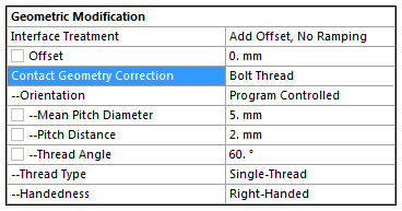
Bolt Thread
This geometry correction option enables you to model bolt threads. For a 2D axisymmetric model, only edge-to-edge scoping is supported. For a 3D model, only face-to-face scoping is supported. For additional technical information about this feature, see the Simplified Bolt Thread Modeling section of the Mechanical APDL Contact Technology Guide.
Tip: When you specify the option, it is strongly recommended that you have a refined mesh. See the Sizing Group (Category) sections of the Meshing User's Guide for additional information about mesh refinement.
Support Requirements
In order to use the option, note the following.
For 3D models, when the Orientation property is set to , the edges specified for the Contact and Target properties of the selected cylinders must be circular edges.
The Contact Geometry Correction property is available for all contact Type settings except for .
The Behavior properties and are not supported.
It is recommended that you do not set the Detection Method to either or .
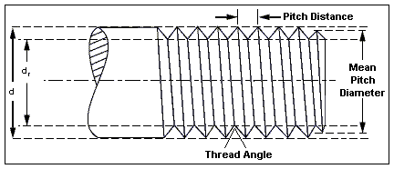
The diameter of the solid model (bolt and nut bodies) should be based on the major diameter (d).
Property Descriptions
The following properties are visible when Contact/Target Geometry Correction is set to .
- Orientation
Property options include:
(default): A contact condition with Contact/Target Geometry Correction property defined as , is fully defined only when cylindrical contact conditions are detected by the application, otherwise, manual specifications are required.
: when is selected, the following additional properties display. These properties define the coordinate systems that are used to generate the axis around which the bolt is oriented. They do not correspond to the starting and ending point of the bolt threads.
Starting Point
Ending Point
- Mean Pitch Diameter
This property defines the average diameter of the threaded bolt.
- Pitch Distance
This property defines the length of the thread pitch.
- Thread Angle
This property defines the angle of the thread’s inclination.
The following diagram illustrates the Mean Pitch Diameter, Pitch Distance, and Thread Angle.
- Thread Type
This property defines the number of threads on the bolt. Property options include:
- Handedness
This property defines the bolt as either right or left handed. Property options include:
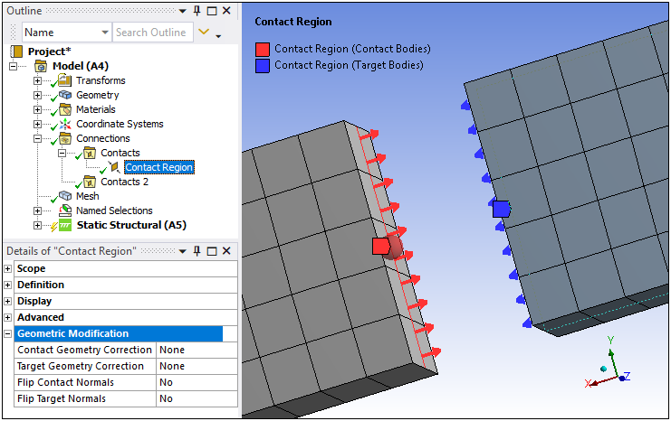
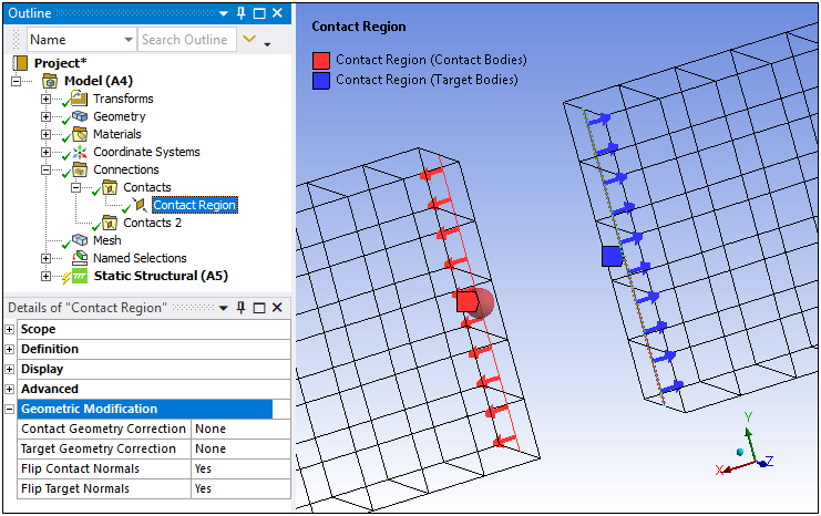
Flip Contact/Target Normals
The Flip Contact Normals and the Flip Target Normals properties enable you to invert the normal direction of edge contacts on 2D surface bodies. You use the Element Normals property of the Display category in combination with these properties to display the normal directions of the edge elements in contact and, as needed, invert the direction.