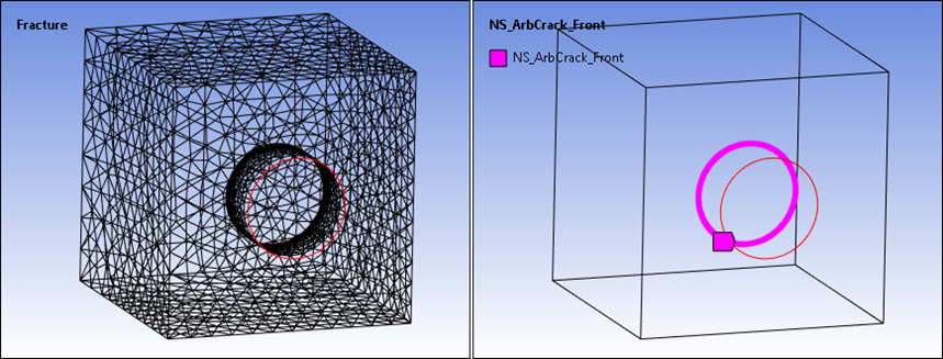
The Meshing application supports fracture meshing capabilities enabling you to insert multiple surface cracks and/or multiple embedded cracks (Elliptical and Ring) into the body mesh. This fracture mesh can then be used to analyze crack fronts in Static Structural and Transient structural analyses. Fracture meshing uses a Fracture object that can contain multiple Arbitrary Crack, Semi-Elliptical, Elliptical Crack, Ring Crack, Corner Crack, Edge Crack, Through Crack, and/or Cylindrical Crack objects.
Go to a section topic:
Overview
The following figure illustrates many of the components of fracture meshing that are discussed throughout this section. This figure is a sliced top view of a semi-elliptical crack.
Overview of Fracture Meshing Components
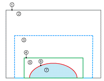
Body to which the semi-elliptical crack is scoped.
Base mesh, which always consists of quadratic tetrahedron elements. For the generation of fracture mesh, the base mesh inside and surrounding the region of the buffer zone (3) must be a quadratic tetrahedron mesh. However, non-tetrahedron/linear mesh may exist farther away from the buffer zone on the same body to which the semi-elliptical crack is scoped.
Buffer zone, which is always filled with quadratic tetrahedron elements.
Interface between the buffer zone (3) and the fracture affected zone (5), illustrated by the green line. Contact pair 1 is defined at the interface between the elements in the buffer zone and the elements in the fracture affected zone.
Fracture affected zone, which is filled with quadratic elements (hex and wedge).
Crack front, located along the crack shape and illustrated by the red line. The crack shape is semi-elliptical.
Discontinuity planes, illustrated by the light blue shading. Consist of two planes at the same location (the crack front plane).
For semi-elliptical, elliptical, or ring cracks, you use the Mesh Method property to specify the mesh as either (default) or .
Note: When you specify the Mesh Method property as to mesh a supported analytical crack, the application does not create the Fracture Affected Zone (Step 5) and as a result the Interface (Step 4) does not exist. All other components remain the same.
Characteristics and Limitations of Fracture Meshing
Note the following information when using fracture meshing:
- General
Fracture meshing is a post mesh process which occurs during a separate step after the base mesh is generated. If you do not generate a base mesh before you invoke Generate All Crack Meshes, the base mesh is generated first and the crack meshing occurs in a separate step after base meshing is complete.
When the Mesh Method property is set to , then meshing any analytical crack does not generate contact pairs in the interface region of the crack mesh and base mesh.
Note: When the free surfaces of a solid body intersect with either an Elliptical Crack or a Ring Crack, the setting for the Mesh Method property is not supported.
For analytical cracks with a Tetrahedron mesh, the Largest Contour Radius and Mesh Contours properties affect the crack mesh only when the Front Element Size property is set to . These properties do not have an effect on the crack mesh when the Front Element Size property is user defined. For Arbitrary cracks the Largest Contour Radius and Mesh Contour properties do not have an effect on the crack mesh.
For the base mesh inside and surrounding the region of the buffer zone, fracture meshing supports quadratic tetrahedron elements only. Linear elements may exist farther away from the buffer zone on the same body to which the analytical crack or arbitrary crack is scoped.

Fracture meshing is a part-based meshing operation. It is supported for all part/body-based tetrahedron mesh methods.
Fracture meshing does not support insertion of a crack that spans multiple bodies.
The fracture mesh overrides the settings of the base mesh. You can insert an analytical crack on topology to which a sizing control, match control, or mapped Face Meshing control is already applied. However, fracture meshing does not respect sizing controls. It will also eliminate or disable a match or mapped Face Meshing control. For example and as illustrated below, fracture meshing has overwritten a mapped Face Meshing control.

Fracture meshing does not support mesh refinement.
Fracture meshing is supported for static structural and transient structural analyses only.
Crack insertion does not alter the geometry/topology of a model.
For Error Limits, fracture meshing supports the Standard Mechanical option only.
Once inserted, the Fracture folder object:
Cannot be suppressed.
Can only be deleted if the folder is empty.
All analytical crack objects can be suppressed, deleted, or duplicated. When a crack definition changes after meshing, only the Fracture object in the tree Outline is invalidated.
The plane for all analytical cracks except the Cylindrical Crack, always lies in the X-Z plane of the specified coordinate system.
The major radius of the semi-elliptical crack/elliptical crack/ring/corner crack grows in the Z direction. The minor radius of the elliptical crack/ring crack grows in the X direction of the specified coordinate system, and the minor radius grows of the semi-elliptical crack in the positive X direction of the specified coordinate system.
When you use the Part Transform feature on a meshed model that has a crack specified on a part, each time you change the Part Transform, the application clears the mesh on the body with cracks and requires re-mesh of the crack-based body.
- For Semi-Elliptical Cracks
Fracture meshing supports semi-elliptical crack insertion on planar surfaces and curved surfaces. For curved surfaces, you can insert semi-elliptical cracks on convex or concave surfaces. If you try to insert a single crack that extends across a surface that has both types of curves, crack insertion may fail.
Fracture meshing does not support semi-elliptical crack insertion at a corner.
The specified coordinate system should lie on the surface of the body to which the semi-elliptical crack is scoped. If it does not, and the Project to Nearest Surface property is set to , the software projects the coordinate system onto the body’s surface and modifies the center of the ellipse, as shown below.
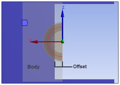
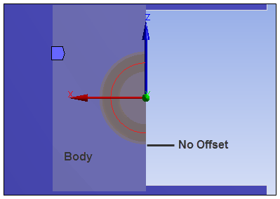
In this case, you will need to define the Hit Point Normal and orient the primary axis. The center of the ellipse is moved in the X direction so the major radius of the semi-elliptical crack grows in the Z direction, and the minor radius grows in the positive X direction of the specified coordinate system. The offset projects back to the surface of the body, making the offset close to 0. The illustration below shows the resultant mesh. For more information on creating a coordinate system aligned with a hit point, see the Creating a Coordinate System Based on a Surface Normal section of the help.
You can use the Annotation Preferences dialog box to toggle the visibility of annotations for cracks. For details, refer to the Probe, Maximum, and Minimum section of the help.
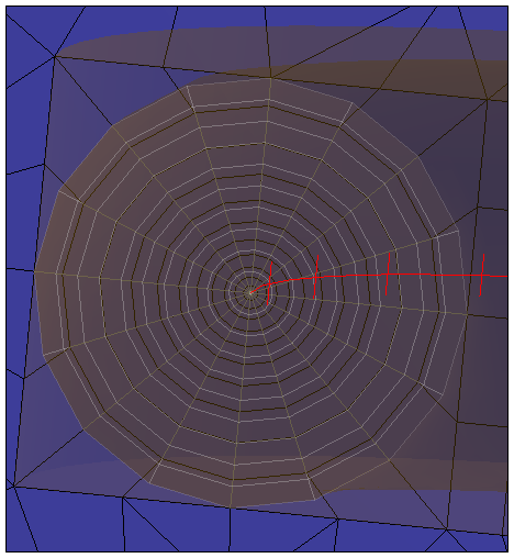
As illustrated by the figure below, the mesh generated for the mesh contours (black lines) will not necessarily match the preview of the mesh contours (white lines).
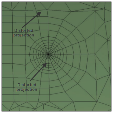
When cracks are inserted in curved surfaces, the projection of the crack template on the surface may be slightly distorted on the template, as shown in the following figure.
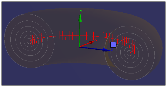
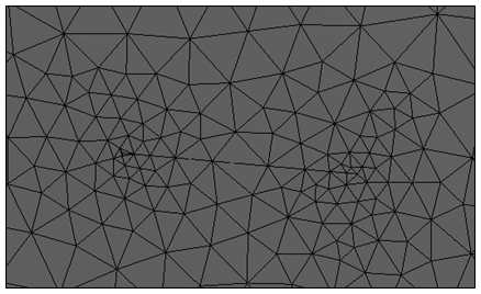
Illustrated below is the graphics preview of a semi-elliptical crack that uses the Tetrahedrons Mesh Method. The graphics preview always shows the structured hex dominant shape irrespective of the mesh method selection. It does not accurately represent the generated crack mesh as compared to the generated crack mesh image. However, you can use the preview to examine the effect of the mesh parameters on the generated crack mesh.
Graphics Preview
Generated Crack Mesh - Tetrahedrons Mesh Method
- For Arbitrary Cracks
Arbitrary cracks only support crack mesh generation using as the Mesh Method.
Arbitrary crack supports both planar and non-planar crack.
Arbitrary cracks support surface, embedded, through, and corner cracks.
Fracture meshing of Arbitrary cracks automatically detects proper intersection points between the crack surface body and its scoped geometry selection to extract the crack front. The image shown below shows that even if the crack surface is extended beyond the surface of the scoped geometry selection, the crack front nodes only include the intersection points and the points that are located inside of the surface.

When generating the mesh for an Arbitrary crack, it is required that the coordinate system is selected such that the crack surface is located on both sides of the Z axis and that the crack top face is located in the positive Y axis.
You can define multiple cracks on the same body as long as their buffer zones do not intersect.
The arbitrary crack mesh illustrated below displays the tetrahedrons as the mesh method used to generate non-planar crack mesh. The crack front nodes of the generated crack mesh are extracted from the intersection points of the crack surface to the cylinder body.

- Embedded and Intersecting Arbitrary Crack Mesh
You can also specify a crack surface body that is embedded inside a solid body or intersecting the free surfaces of a solid body. Crack mesh generation using these crack surfaces enables you to insert:
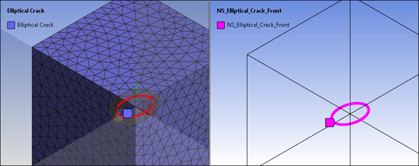
Arbitrary Elliptical Crack
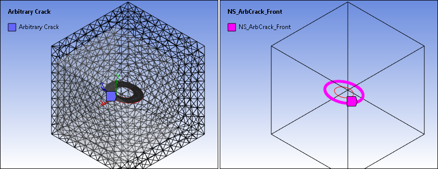
Arbitrary Ring Crack
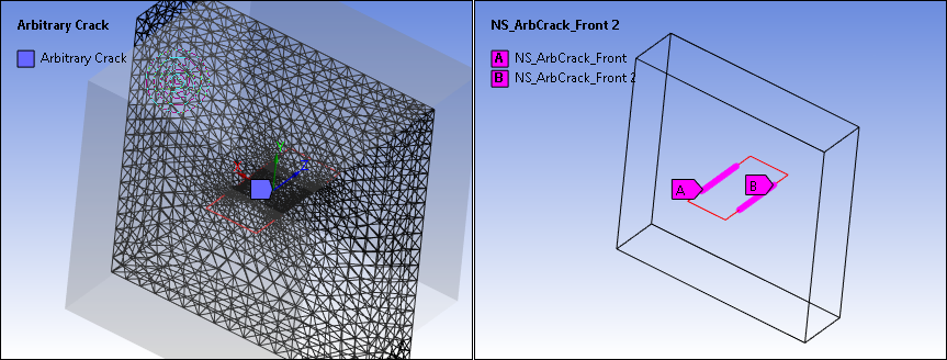
Arbitrary Through Crack
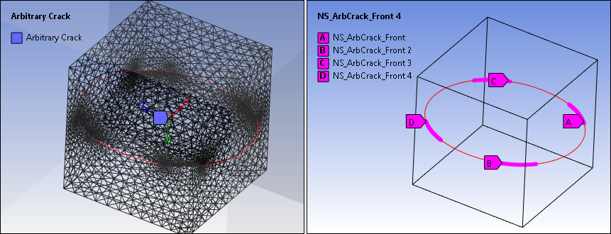
Arbitrary Crack Intersecting Multiple Corners
Arbitrary Cylinder Crack
