


Inserts a crack, with a cylindrical shape, into a solid body.
 |
Object Properties
The Details Pane properties for this object include the following.
| Category | Properties/Options/Descriptions |
|---|---|
|
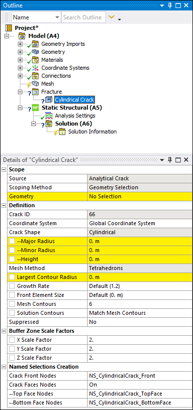
Scope |
Source: Read-only property set to Analytical Crack Scoping Method: Read-only property set to Geometry Selection. Geometry: Use the Body selection filter to pick a solid body, click in the Geometry field, then click . |
|
Definition |
Crack ID: A read-only property that displays a unique system generated identification value. The application uses this identifier when creating solution identifiers for fracture parameters. Coordinate System: Specify the coordinate system that defines the orientation of the crack. The X axis of the specified coordinate system must be directed towards the axis of the cylindrical crack and the first crack front always lies in the Y-Z plane of the specified coordinate system. Crack Shape: Read-only property set to Cylindrical. Major Radius: Specifies the major radius, which defines the
size of the crack shape along the Y axis. Enter a value greater than
Minor Radius: Specifies the minor radius, which defines the
size of the crack shape along the Z axis. Enter a value greater than
Height: Specifies the height of the cylindrical crack to be inserted. The height is defined from the origin of the coordinate system (starting face of the cylinder) to the other end of the cylinder. You can parameterize this property. Important: If the specified height is less than the gap between the origin of the coordinate system and the free surface of the solid geometry, the mesh generates two crack fronts and two crack surfaces. Otherwise, the mesh generates a single crack front and two crack surfaces. Mesh Method: This is a read-only property set to , the only supported method. Largest Contour Radius: Specifies the largest contour
radius for the crack shape. Enter a value greater than Growth Rate: It specifies the factor with which the mesh
layers will grow along the radius of the crack. Specify a value greater than
Front Element Size: It specifies the element size for the
crack front. The default value is computed using crack length. Specify a value
greater than Mesh Contours: Specifies the number of mesh contours for
the crack shape. The value you enter must be equal to or greater than
Note: The maximum number of mesh contours the Geometry window can display is 100. However, you can specify a higher value and the application will process it accordingly. Solution Contours: Specifies the number of mesh contours
for which you want to compute the fracture result parameters. The value you enter
must be less than or equal to the value of Mesh Contours, and
cannot be greater than Suppressed: Toggles suppression of the object. The default is No. The application automatically suppresses the crack object if the scoped body becomes suppressed. |
|
Buffer Zone Scale Factors |
This category includes the following properties:
These properties control the size of the buffer zone in the X, Y, and Z
directions, relative to the dimensions of the crack. For each scaling parameter, use
the slider to set a value from |
|
Named Selections Creation |
Named Selections are created automatically when the fracture mesh is generated. These Named Selections are a special type of Named Selection. For more information about this category and its properties, see the Defining a Cylindrical Crack section as well as the Special Handling of Named Selections for Crack Objects section. For information about Named Selections in general, refer to Named Selections in the Mechanical Object Reference. |
Tree Dependencies
Insertion Methods
Select the Fracture object and select the Cylindrical Crack option from the Crack group on the Fracture Context Tab. You can also right-click the Fracture object and select the crack from the menu. Any currently inserted cracks also provide this right-click menu.
Right-click Options
In addition to common right-click options, relevant right-click options for this object include:
Insert >
Arbitrary Crack
Semi-Elliptical Crack
Elliptical Crack
Ring Crack
Corner Crack
Edge Crack
Through Crack
Cylindrical Crack
Pre-Meshed Crack
Crack Initiation
Commands
Generate All Crack Meshes
Suppress
API Reference
See the Cylinder Crack section of the ACT API Reference Guide for specific scripting information.