


Defines a semi-elliptical crack based on an internally generated mesh to analyze crack fronts by use of geometric parameters.
 |
Object Properties
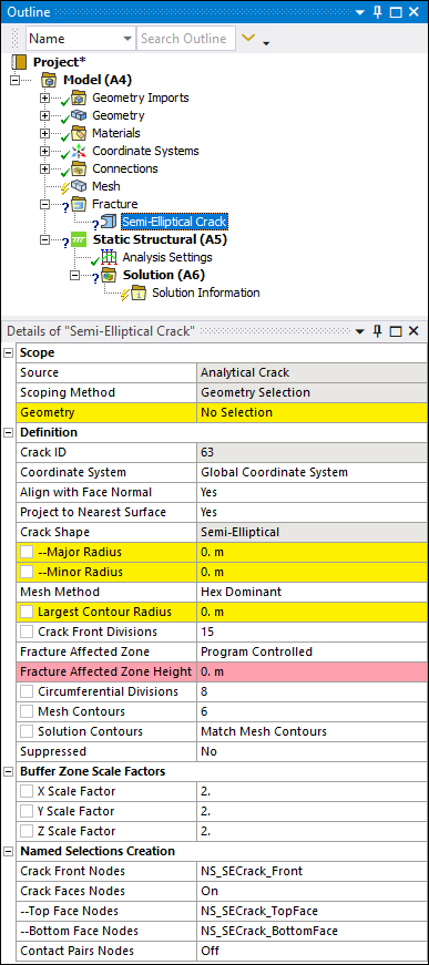
The Details Pane properties for this object include the following.
| Category | Properties/Options/Descriptions |
|---|---|
|
Scope |
Source: Read-only and always set to Analytical Crack for Semi-Elliptical Cracks. Scoping Method: Read-only and always set to Geometry Selection when defining cracks. Geometry: Use the Body selection filter to pick a solid body, click in the Geometry field, then click . |
|
Definition |
Crack ID: A read-only property that displays a unique system generated identification number ID for the crack object. The application uses this identifier when creating solution identifiers for fracture parameters. Coordinate System: Specifies the user-defined coordinate system that defines the position and orientation of the crack. Align with Face Normal: Defines the Crack Coordinate System orientation. Options include (default) and . Project to Nearest Surface: Defines the Crack Coordinate System origin. Options include (default) and . Crack Shape: Read-only and always set to Semi-Elliptical. Major Radius: Specifies the major radius, which defines the
size of the crack shape along the Z axis (that is, the width of the crack). The
specified value must be greater than Minor Radius: Specifies the minor radius, which defines the
size of the crack shape along the X axis (that is, the depth of the crack). The
specified value must be greater than Mesh Method: Selects the mesh method to be used to mesh the semi-elliptical crack. Options include (default) and . Largest Contour Radius: Specifies the largest contour
radius for the crack shape. Enter a value greater than
Growth Rate (Mesh Method set to
only): Specifies the factor with which the
mesh layers will grow along the radius of the crack. Specify a value greater than
Crack Front Divisions (Mesh Method set
to only): Specifies the number of divisions
for the crack front. The value must be equal to or greater than
Front Element Size (Mesh Method set to
only): Specifies the element size for the
crack front. Default value is computed from crack's ellipse perimeter, which is
crack ellipse perimeter/100. Specify a value greater than
Fracture Affected Zone(Mesh Method set to only): The fracture affected zone is the region that contains a crack. The Fracture Affected Zone control determines how the fracture affected zone height is defined. When set to Program Controlled, the software calculates the height, and Fracture Affected Zone Height is read-only. This is the default. When set to Manual, you enter the height in the Fracture Affected Zone Height field. Fracture Affected Zone Height(Mesh Method set to only): This value specifies two things: 1) the height of the Fracture Affected Zone, which is in the Y direction of the crack coordinate system, and 2) the distance in totality by which the Fracture Affected Zone is extended in the positive and negative Z direction of the crack coordinate system from the crack front extremities. Circumferential Divisions (Mesh Method
set to only): Specifies the number of
circumferential divisions for the crack shape. Your entry must be a multiple of
Mesh Contours: Specifies the number of mesh contours for
the crack shape. Your entry must be equal to or greater than
Solution Contours: Specifies the number of mesh contours for which you want to compute the fracture result parameters. The value must be less than or equal to the value of Mesh Contours, and cannot be greater than 99. By default, the value is Match Mesh Contours, indicating the number of Solution Contours is equal to the number of Mesh Contours. Entering 0 resets the value to Match Mesh Contours. Suppressed: Toggles suppression of the Crack object. The default is No. The Crack object is suppressed automatically if the scoped body is suppressed. |
|
Buffer Zone Scale Factors |
Buffer Zone Scale Factors It controls the size of the buffer zone in the X, Y, and Z directions, relative
to the dimensions of the crack. For each scaling parameter, use the slider to set a
value from
|
|
Named Selections Creation |
Named Selections are created automatically when the fracture mesh is generated. These Named Selections are a special type of Named Selection. For details, refer to the Performing a Fracture Analysis and the Special Handling of Named Selections for Crack Objects sections for more information. |
Tree Dependencies
Insertion Methods
Select the Fracture object and select the Semi-Elliptical Crack option from the Crack group on the Fracture Context Tab. You can also right-click the Fracture object and select the crack from the menu. Any currently inserted cracks also provide this right-click menu.
Right-click Options
In addition to common right-click options, relevant right-click options for this object include:
Insert >
Arbitrary Crack
Semi-Elliptical Crack
Elliptical Crack
Ring Crack
Corner Crack
Edge Crack
Through Crack
Cylindrical Crack
Pre-Meshed Crack
Crack Initiation
Commands
Generate All Crack Meshes
Suppress
API Reference
See the Semi-Elliptical Crack section of the ACT API Reference Guide for specific scripting information.