This section presents an example of some common joint configuration steps for a model of a pendulum created from two links, as illustrated below:
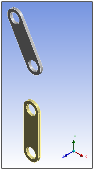
To achieve the desired result, two revolute joints were created and configured:
The first joint is intended to allow rotation of the top link's upper hole referenced to a stationary point (Body-Ground Revolute Joint).
The second joint is intended to allow rotation of the bottom link's upper hole referenced to the top link's lower hole (Body-Ground Revolute Joint).
Tip: Make sure that the Auto Rename Connections preference (Options > Connections > Default) is set to .
The following steps illustrate the steps of a common joint configuration:
After attaching the model to Mechanical, create the first revolute joint.
Select the Connections object, open the drop-down menu, (Connections Context Tab, and select . The new joint object becomes the active object in the Outline.
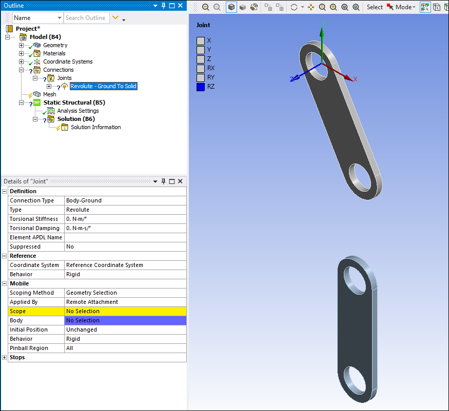
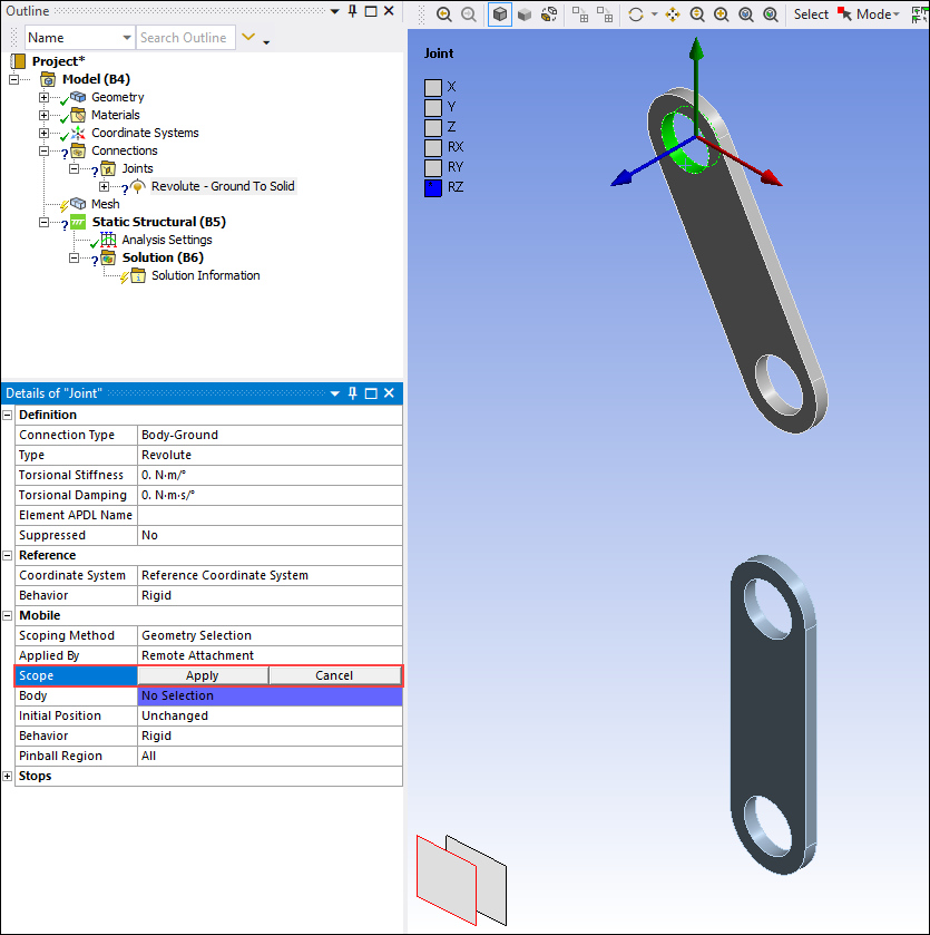
Scope the Mobile side of the first revolute joint to the top link's upper hole.
Select the inner surface of the upper hole and then under Mobile category in the Details view, select the Scope field and click the button.
Create the second revolute joint.
Open the drop-down menu from the Connections Context Tab and select . The new joint object becomes the active object in the Outline.
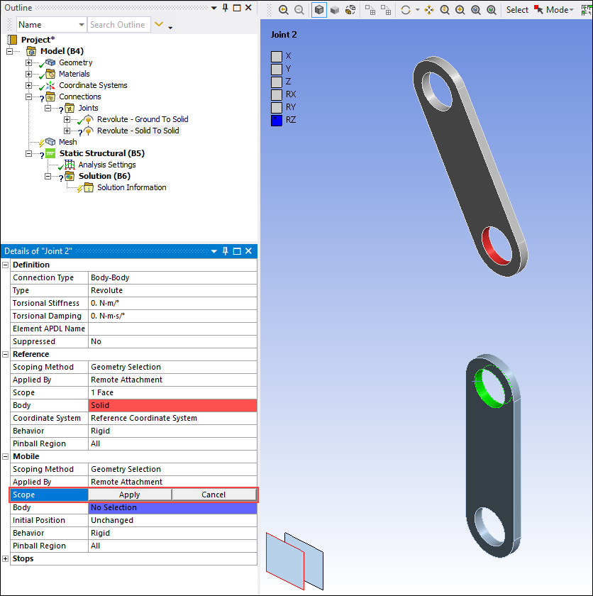
Scope the Reference side of the second joint to the top link's lower hole.
Select inner surface of hole and the under Reference category in the Details, select the Scope field and click the button.
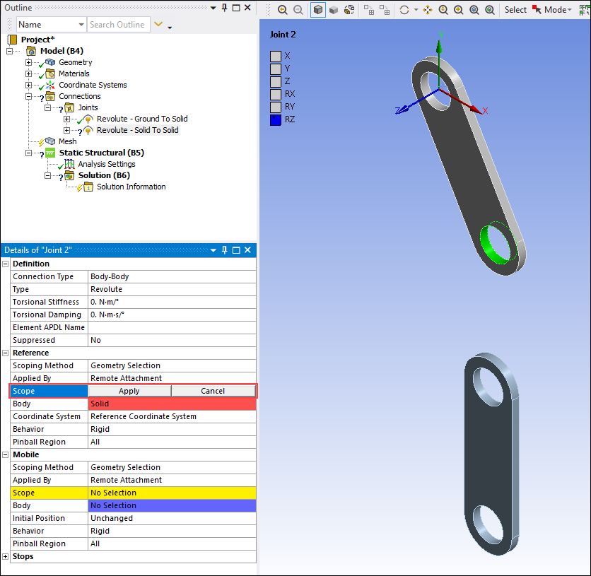
Scope the mobile side of the second joint to the bottom link's upper hole.
Select inside surface of hole, then under Mobile category in the Details view, select the Scope field and click the button.
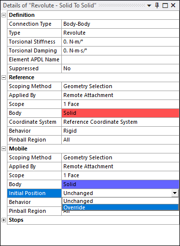
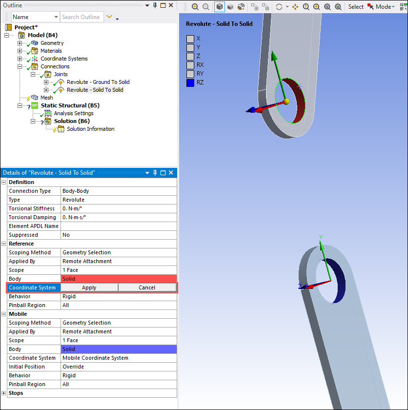
The two holes that will form the second joint need to be properly aligned. To align the holes, you need to indicate that the two holes need to match. To achieve this, first create a coordinate system for the mobile side of the second joint, and then align the Mobile and Reference coordinate systems.
Highlight the second joint, Revolute - Solid To Solid, in the tree and select from the drop-down menu of the Initial Position property. Note that a new Coordinate System property displays.
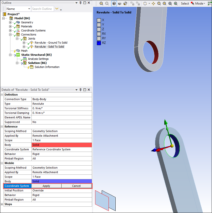
Scope the new mobile coordinate system to the back edge of the bottom link's upper hole.
Select the back edge of the bottom link's upper hole, then under Mobile category, select the Coordinate System field, and then click the button.
Scope the existing Reference Coordinate System to the back edge of the top link's lower hole.
Select the back edge of the top link's lower hole, and then under Reference category, select the Coordinate System field and then click the button.
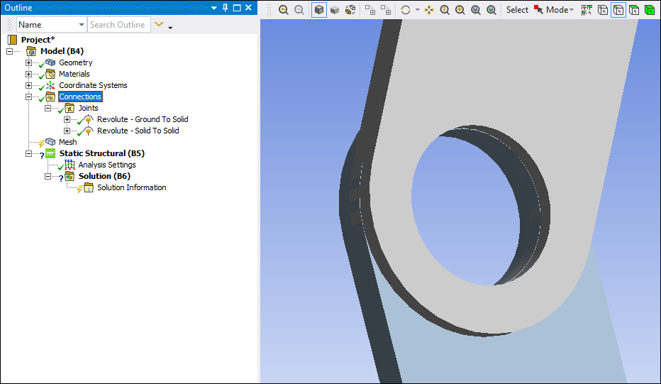
The above steps have correctly assigned the coordinate systems so that the holes can be aligned and the revolute joint can operate properly.
To verify, highlight the Connections object in the tree and select the option on the Context tab.
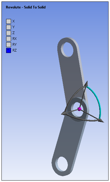
Establish the initial position of each joint.
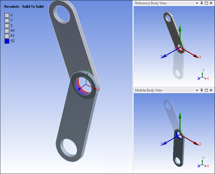
Highlight the body-to-body joint object in the tree and select the option on the Context tab. The joint is graphically displayed according to your configuration. In addition, a triad appears with straight lines representing translational degrees of freedom and curved lines representing rotational degrees of freedom. Among these, any colored lines represent the free degrees of freedom for the joint type. For the joint that is being configured, the translational displacement degrees of freedom always follow the Geometry units rather than the current Mechanical units.
By dragging the mouse cursor on a colored line, the joint will move allowing you to set the initial position of the joint through the free translational or rotational degrees of freedom.

For rotations, holding the [Ctrl] key while dragging the mouse cursor will advance the rotation in 10 degree increments. You can also type the value of the increment into the Delta field on the Context tab. Selecting the option again cancels the joining and positioning of the joint.
Create the joints.
After configuring a joint's initial position, click the option to create the joint. At this point, you also have the option of returning the configuration to the state it was in before joint creation and upon attaching to Mechanical by selecting the option.
Constraints on joints such as stops or locks are fully supported by the Configure tool.
Note: Unexpected results may occur when configuring radial gaps.
Note: When stops or locks are set on joints and a configure operation leads to the violation of corresponding bounds, an error message, which reads Fail to Configure pops up in Mechanical.