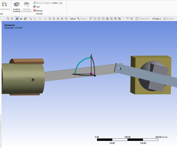
This section describes the steps for configuring a single body within a system of multiple bodies.
In this example, the body to be configured is linked to other bodies in the system by two revolute joints. Hence, applying a transform to this body will result in updating body transforms along the entire chain of bodies.
To configure a body, follow these steps:
Pick a face, edge, or corner of a body using the Smart Select button.
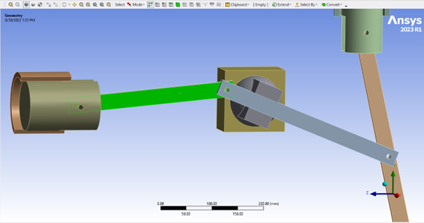
In the Mechanical tree, select Geometry to make the Body Configure button visible.
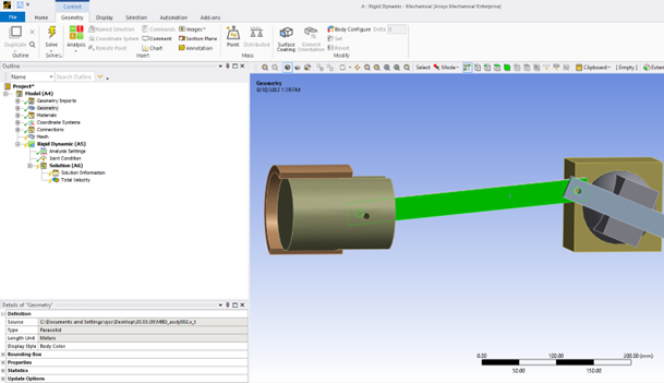
Click Body Configure to make a local coordinate system appear on the selected entity. This coordinate system is acting as a handle on the selected body.
Note: When selecting a face or edge, the configure coordinate system is oriented with respect to the surface normal. When selecting a body or vertex, the axes of the configure coordinate system are aligned with the global axes, not the inertia axes.
Note: The origin of the newly created coordinate system is different from the origin of the joint coordinate system, in case one is already attached to the body to configure. The user transform is derived from the origin of the new coordinate system.
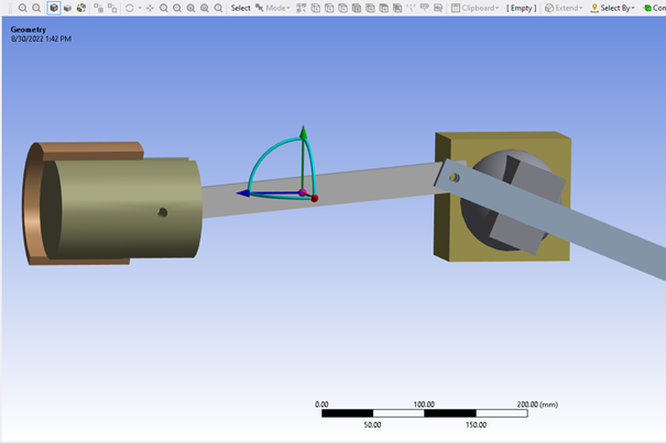
From the local coordinate system, pick a degree of freedom in translation or rotation. In the image below, a rotation around the x-axis is selected.
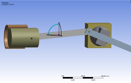
Long-press the cursor on the body and drag it along the selected degree of freedom.
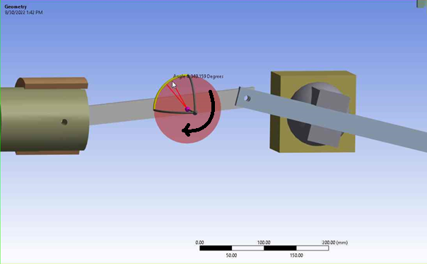
The selected body must follow the transform you specified and move the entire mechanism accordingly.
For optimal accuracy when applying the transform, enter a value in the Delta ribbon. Regarding length, the quantity is expected to be expressed in the unit system currently active in Mechanical. With respect to rotational degrees of freedom, the angle is expected to be expressed in degrees.
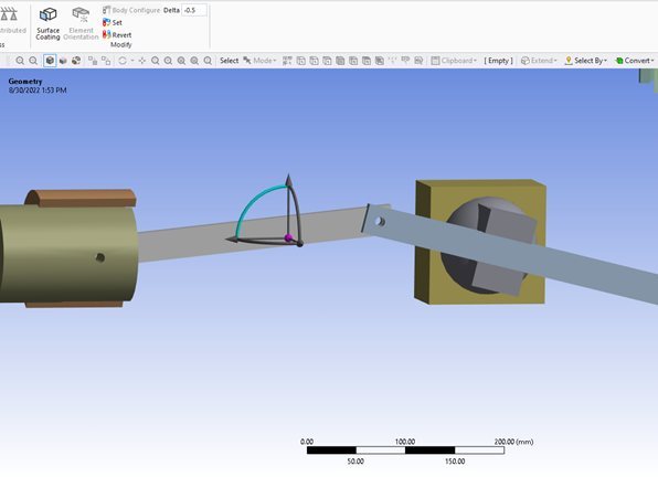
Once a transform is applied, you can set the model in the resulting configuration or revert changes. Click the Set or Revert button to perform either action.
