


Defines mesh connections/contact matches between selected topologies. Includes global settings in Details that apply to all Mesh Connection or Contact Match child objects.
Note: See the object reference pages for Mesh Edit and Node Merge Group for information about other objects related to Mesh Connections, Contact Matches, and Mesh Editing.
 |
Object Properties
The Details Pane properties for this object include the following.
| Category | Properties/Options/Descriptions |
|---|---|
|
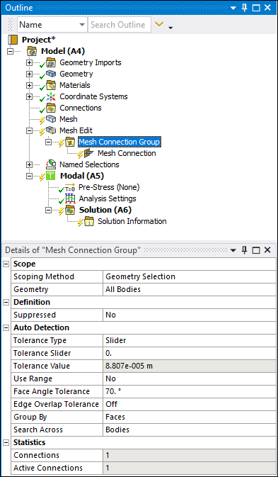
Scope |
Scoping Method: Geometry Selection (default) or Named Selection. Geometry: Visible when the Scoping Method is set to Geometry Selection. Named Selection: Visible when the Scoping Method is set to Named Selection. |
|
Auto Detection |
Tolerance Type: Options include , , and . Bodies in an assembly that were created in a CAD system may not have been placed precisely, resulting in small overlaps or gaps along the connections between bodies. You can account for any imprecision by specifying detection tolerance. This tolerance can be specified by a value when this property is set to or , or sheet thickness of surface bodies when the type is set to . Tolerance Slider: Appears when the Tolerance Type property is set to . To tighten the mesh connection or contact match detection, move the slider bar closer to +100 and to loosen the detection, move the slider bar closer to -100. A tighter tolerance means that the bodies have to be within a smaller region (of either gap or overlap) to be considered; a looser tolerance will have the opposite effect. Be aware that as you adjust the tolerance, the number of mesh connection pairs or contact matches could increase or decrease. Tolerance Value: Appears when the Tolerance Type is set to or . It is a read-only property if the Tolerance Type is set to and displays the tolerance value based on the slider setting. When the Tolerance Type is set to , you can enter an exact distance for the detection tolerance. Thickness Scale Factor: Displays when the
Tolerance Type property is set to . The default value is Use Range: Appears if the Tolerance Type property is set to or . Options include and (default). If set to , mesh connection detection searches within a range from Tolerance Value to Min Distance Value inclusive and the following additional properties display:
Group By: For mesh connections, options include and (default). For contact matches, options include , (default), , and . This property allows you to group the automatically generated mesh connection or contact match objects. For example, setting Group By to for a mesh connection group means that mesh connection faces and edges that lie on the same parts will be included into a single mesh connection object. Search Across: Enables automatic detection through the following options:
Face Angle Tolerance: For faces that will be excluded
from the proximity detection pair, this property defines the minimum angle between
the primary face and secondary edge entity above which the two face pairs will be
ignored from proximity detection. The default value is
Edge Overlap Tolerance: This tolerance value is the
minimum percentage that an edge may overlap the face and is included as a valid
proximity detection pair. The default value is |
|
Statistics |
Connections: Displays the number of connections associated with this parent object. Active Connections: Displays the number of connections that are currently active for this parent object (that is, not Suppressed). |
Tree Dependencies
Insertion Methods
Use any of the following methods after highlighting the Mesh Edit object or another Mesh Connection Group or Contact Match Group object:
Click or on the Model Context Tab.
Right-click object or on another / object or in the Geometry window; then or .
Right-click Options
In addition to common right-click options, relevant right-click options for this object include:
>
Suppress/Unsuppress
Enable/Disable Transparency
Create Named Selection
API Reference
See the Mesh Connection Group section of the ACT API Reference Guide for specific scripting information.