The following procedure describes the steps to specify a General Axisymmetric object.
Once you have imported a surface geometry or a base mesh model into Mechanical, select the Model object and then select the Symmetry option from the Model Context Tab. Alternatively, you can right-click on the Model object or within the Geometry window and select > from the context menu.
Select the Symmetry folder and then select the General Axisymmetric option from the Symmetry Context Tab. Alternatively, you can right-click on the Symmetry folder object or within the Geometry window and select > from the context menu.
Specify the desired Geometry. Only Body scoping is supported. You can scope any planar surface body.
Using the Nodal Planes property, enter your desired number of planes on which nodes should be generated. The entry for this property can be either
1or3through12. A Nodal Planes entry of 2 is not supported.As needed, modify the Coordinate System property. The application uses the Global Coordinate System option as the default setting. You can specify a local coordinate system.
Specify the Axis property. This property specifies the axis about which the mesh nodes are generated. Options include , , and .
Note: The specified Axis must lie along the selected body, it cannot intersect the body. And, the Axis specified must be on the same plane as the selected surface body.
Change the default settings of the Nodal Planes Visible property as desired. The default setting displays planes (as specified in the Nodal Planes property) or you can set the property to and select the number of planes you want to display for the mesh and result objects. Enter a consecutive range based on the number of Nodal Planes, such as 1-6 or 6-12.
Note: When you change Graphics Options:
The application clears all results. It is necessary to reevaluate the results.
For the option, the display of result Min and Max values is for the specified range of planes, not the entire model.
Refer to General Axisymmetric Overview section for additional information, such as load application, limitations, and results options.
Specification Support Examples
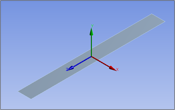
In the example illustrated below, a coordinate system is specified at the centroid of the geometry. As you can see, all three axes of this system cut through the geometry. As a result, you cannot specify this coordinate system and any of its axis for a General Axisymmetric object.
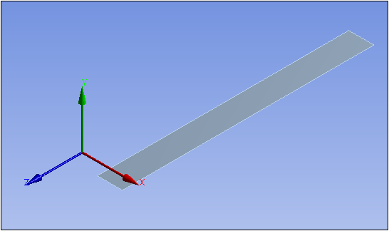
In this example, the X- Axis of the coordinate system cuts through the geometry. As a result, it cannot be specified for the Axis property. The Y-Axis is not in the same plane as the surface body so it cannot be specified for the Axis property. For this example, you can use only the Z-Axis as the axisymmetric axis.