For three-dimensional (3D) Static Structural analyses only, the General Axisymmetric feature enables you to create an axisymmetric mesh, in the circumferential direction, on a surface body model that is based on specified nodal planes and an axis. This feature supports edge and vertex scoping only. Additionally, from these surface model edges and vertices, you can generate three-dimensional node-based Named Selections that you can then use as scoping items for other simulation options such as loading conditions and/or results. An axisymmetric model created using this feature greatly reduces the modeling and analysis time compared to that of an equivalent 3D model.
See the General Axisymmetric Workflow in Mechanical section for the steps to use the feature.
| Go to a section topic: | |
Element Description
This feature uses the Mechanical APDL elements SOLID272 and SOLID273. See the General Axisymmetric Elements section in the Mechanical APDL Element Reference or review the pertinent sections of the Mechanical APDL Theory Reference for additional information.
Limitations
The Axis of symmetry you specify should not intersect your surface body and must be in the same plane as the selected surface body. In addition, review the categorized limitations listed below. You cannot use the listed features and capabilities in combination with the General Axisymmetric feature.
All analysis types other than Static Structural analyses.
Non-planar surface bodies.
Element Orientations.
Point Mass and Distributed Mass.
Beams, Bearings, Joints, and Springs.
Beam contact formulation type.
Only bonded contact is supported between General Axisymmetric bodies with one nodal plane.
When the Type property is set to and the Formulation property is set to MPC, only the and options for the Constraint Type property are supported. All other options define force distributed constraints that are not supported for General Axisymmetric contacts.
The Flip Contact Normals and the Flip Target Normals properties cannot be used to invert the normal direction of edge contacts on 2D surface bodies.
For contact between General Axisymmetric bodies that have one nodal plane, make sure that at least one node is constrained in Z direction for the Target body.
Contacts imported from an imported base mesh will lose their mesh scoping after the General Axisymmetric mesh is generated. As a result, it is recommended that you create contacts with geometry scoping after importing a base mesh.
Named Selections defined on faces that are used to define loads or supports.
Element-based and Element Face-based Named Selections defined using Worksheet criteria.
Load and Boundary Condition Limitations
The following load and boundary conditions are not supported:
Fluid Solid Interface
Joint Load and Bearing Load
Line Pressure or Hydrostatic Pressure
Radial loading
Imported Loads other than Imported Body Temperature and Imported Displacement (only).
Simply Supported, Fixed Rotation, Frictional, and Cylindrical supports.
Also note the following with regards to loading and boundary conditions:
Scoping the surface bodies defined using the General Axisymmetric feature to objects such as Symmetry Region, Thickness, Layered Section, Imported Thickness, and Imported Layered Section.
Deformable Behavior is not supported for objects which create or use remote points like Remote Points, Remote loads, Moments, Point Mass, Beam connections, Bearings, Joints, Springs when scoped to General Axisymmetric bodies.
Note the following scenarios where the load direction arrow (annotation) is not displayed in the Geometry window:
Pressure load and Displacement boundary condition defined by with a Cylindrical Coordinate System.
Pressure load defined using the option.
When your analysis includes a Thermal Condition, Imported Body Temperature, Imported Displacement, and/or a Spatially Varying Pressure (Normal To), load variation contours do not display for any of these loads types unless you have the load scoped to nodes using a node-based Named Selection. Otherwise, the variable loading conditions display in purple and there is an annotation in the Geometry window that indicates the load as a "Variable Load."
Path dependent results such as Linearized stress results.
Location Probes (Location Method property set to )
Path, Surface, and Surface Coating scoping methods of results. That is, results cannot be extracted using Construction Geometries.
Convergence for results.
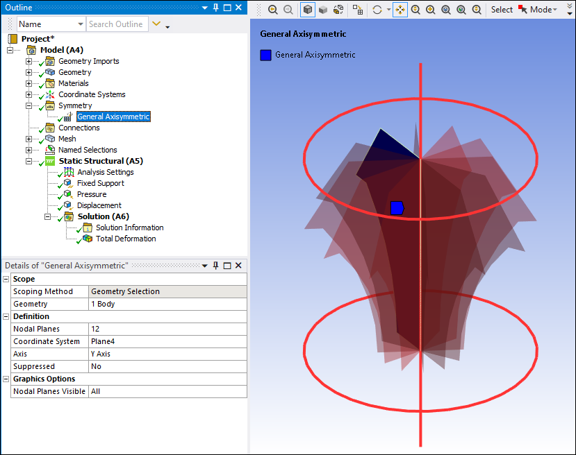
Graphic Display
As illustrated here, when you specify a General Axisymmetric object, the Geometry window automatically displays the axis and the nodal planes around it. The application will generate nodes on these planes.
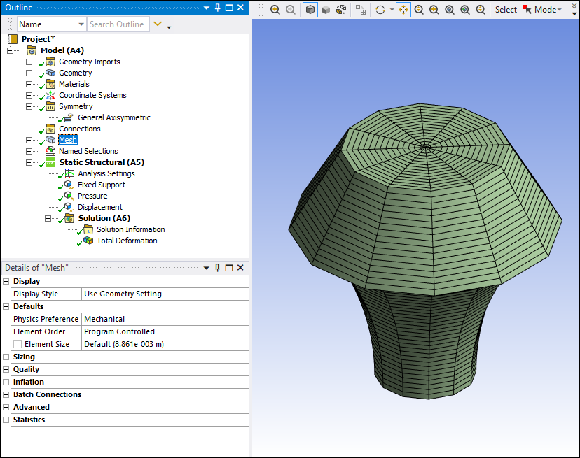
Mesh Generation
Once you fully define the General Axisymmetric object, you can generate the General Axisymmetric mesh using the context (right-click) menu option / on object. The application first creates the base mesh on the surface body and then it generates the General Axisymmetric mesh on all nodal planes in circumferential direction. The example below illustrates a mesh generated for 12 nodal planes.
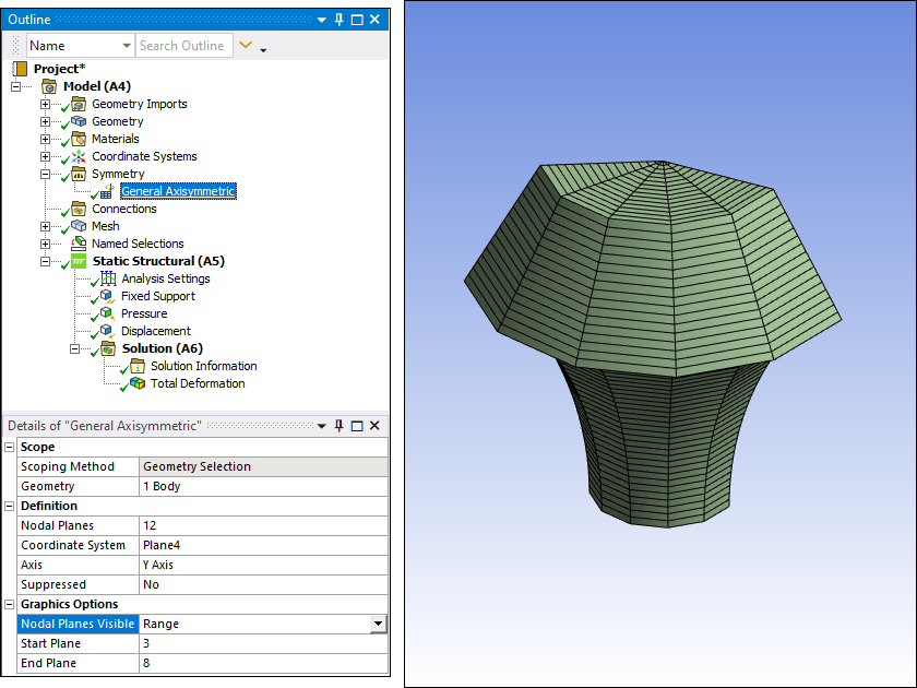
Additionally, here is an example of the mesh with the Nodal Planes Visible property set to ,
and the Start Plane property set to 3 and End Plane property set to 8.
Named Selection Display
As illustrated in the following example, you can create a Named Selection on an edge (or vertex). For this example, you create a node-based Named Selection from the edge-based Named Selection using the context (right-click) menu option Create Nodal Named Selection. This node-based Named Selection represents the circumferential nodes of a full axisymmetric mesh. Node-based Named Selections like this can also be created using the Worksheet.
Contact Support
You use this feature on surface bodies. As a result, you need to specify an edge for contact conditions (contact and target selection). Supported contact combinations include:
The edges of two General Axisymmetric bodies.
A solid surface as the target side and a General Axisymmetric edge as contact side.
A 3D shell as the target side and General Axisymmetric edge as the contact side.
When an edge of a General Axisymmetric body is in contact with a surface or edge of a shell body or with a surface of a solid body, the nodes on the scoped edge in the base nodal plane as well as the equivalent nodes in the circumferential direction form contact. However, if the General Axisymmetric body has only one nodal plane, contact occurs only along the nodes of the edge in the base nodal plane, as illustrated below.
Note: For the Contact Tool , for node-to-surface contact, Pressure displays zeros for results. To display the associated contact force, you must insert a user defined result called CONTFORC.
The application creates:
Asymmetric contact pairs.
Node-to-surface contact pairs (contact elements CONTA175 paired with target elements TARGE170) when the Nodal Planes property value specified on the associated General Axisymmetric objects equals
3-12.2-D node-to-surface contact pairs (contact elements CONTA175 paired with target elements TARGE169), in the case of a true axisymmetric condition (the Nodal Planes property on the associated General Axisymmetric objects set to
1).
Note:
You cannot create contact pairs between two General Axisymmetric bodies with different nodal planes.
Only Bonded contact is supported between General Axisymmetric bodies with one nodal plane.
If the scoped bodies are not in XY plane, contact between General Axisymmetric bodies with only one nodal plane is not supported.
Load/Support Application
When specifying loads and supports on your surface body model, you can:
Apply Direct FE loading conditions, including: Nodal Force, Nodal Pressure, and Nodal Displacement. You can use these loads to specify non-axisymmetric loads.
Apply tensile, compressive, and torsional loading using edge or vertex scoping.
Apply Remote Force, Remote Displacement, and Moments.
Surface effect elements SURF159 are created to apply a Pressure load when the Defined By property is set to and the Applied By property is set to or when the Defined By property set to or .
An Imported Body Temperature load, when applied on General Axisymmetric bodies, uses the Volumetric transfer type when the Mapping Control property is set to (the recommended data mapping type).
For imported loads, if you want to map 2D data onto a General Axisymmetric 3D mesh (NP>1), it is recommended that you set the Dimension property to in the Project Schematic when specifying the External Data. In Mechanical, the load is transferred onto the General Axisymmetric mesh using the 2D Projection property. It is further recommended that you select a cylindrical coordinate system for 2D Projection property in order to transfer the data in circumferential direction.
Important: Loads on General Axisymmetric bodies with one nodal plane may produce torsion. Use constraints along the body plane normal if torsion is not desired.
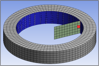
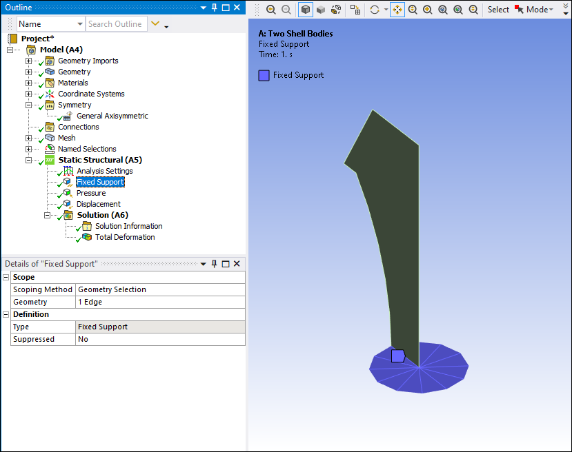
When you scope loads and/or supports to an edge on surface geometry, the solver transfers the load to the nodes of all the nodal planes. This is essentially the same as selecting a face of a full model, as highlighted below.
Edge Scoping on a Fixed Support
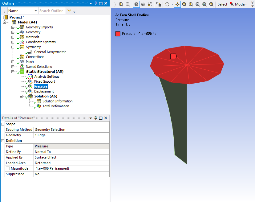
Edge Scoping on a Pressure Load
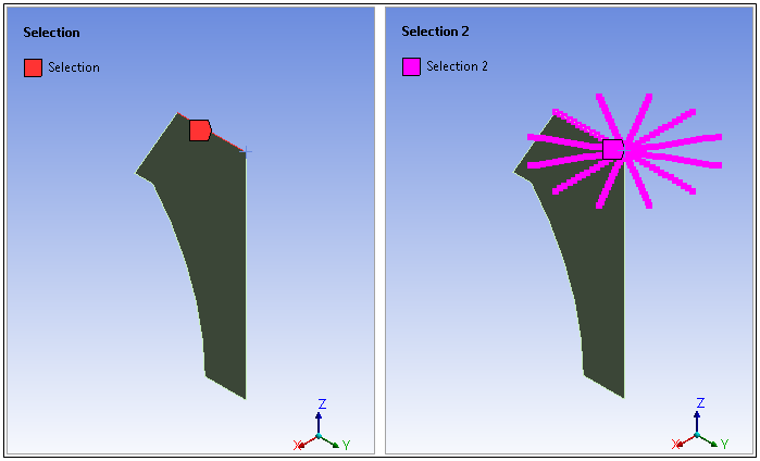
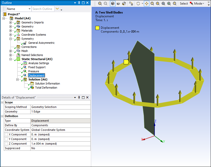
Similarly, and as illustrated here, when you scope a support or load to a vertex, the solver transfers it onto the corresponding nodes from all nodal planes, which is nothing but an edge of a full model.
Vertex Scoping on a Displacement
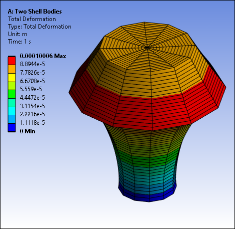
Result Display
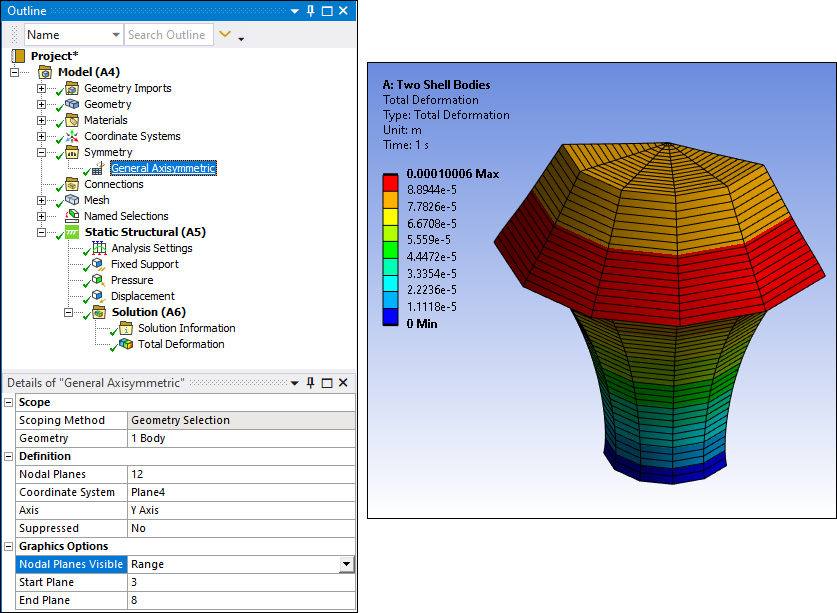
Once solved, result contours for this feature display similar to an equivalent 3D solid model.
This result is an example of the Nodal Planes Visible property set to , and the
Start Plane property set to 3 and End Plane property set to 8.