This example demonstrates the fluid-structure interaction methodology for cyclic symmetry. The model represents a simplified hydro-turbine.
The model consists of an 8-bladed disk in water. The structure is modeled with SOLSH190 elements, and the fluid is modeled with FLUID30 elements. All degrees of freedom are constrained at the inner radius. Real and imaginary pressure loading is applied to surface elements (SURF154) using the CYCOPT,LDSECT command to create an engine order 2 loading.
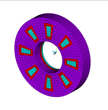
The hydro-turbine model is shown below. The structural elements are blue, and the fluid elements are purple and red, with red indicating the fluid elements that are adjacent to the structural elements.
The geometric and material properties used for the harmonic cyclic analysis are the same as used in Example Modal Cyclic Symmetry Analysis.
All applicable degrees of freedom are used for the cyclic symmetry edge-component pairs. The harmonic response to a pressure load applied on the assembly is computed.
Use the input file given below to perform this example harmonic cyclic symmetry analysis with FSI. The file contains the complete geometry, material properties, and solution options for the finite element model.
/out,scratch
/com, ***********************************************************************
/com, *** Parameters
/com, ***********************************************************************
coord = 6			! 1 = z-axis, 5 = y-axis, 6 = x-axis, 11 = user-defined axis

! Element types
elem1=190			! 185, 186, 187
elem2=30			! 30, 220, 221

! Geometry parameters
nSectors = 8                ! Number of sectors

x1=0.6
x2=0.8
x3=1.2
x4=1.5

sectorAngle=360/nSectors
y0=0.0
y1=5
y2=sectorAngle/2

z0=0.0
z1=0.080
z2=2*0.24

! Harmonic solution parameters
EO = 2              ! Engine order 2 loading
p0=200
freq1=123
freq2=128
freqnum=25

/com, **********************************************************************
parsav

/com, ***********************************************************************
/com, *** Geometry creation
/com, ***********************************************************************

/prep7

wpcsys,1,coord
csys,coord

cyl4,0.0,0.0,x1,y0,x2,y1,(z1-z0)
cyl4,0.0,0.0,x1,y1,x2,y2,(z1-z0)
cyl4,0.0,0.0,x2,y0,x3,y1,(z1-z0)
cyl4,0.0,0.0,x2,y1,x3,y2,(z1-z0)
cyl4,0.0,0.0,x3,y0,x4,y1,(z1-z0)
cyl4,0.0,0.0,x3,y1,x4,y2,(z1-z0)

wpof,,,z1
cyl4,0.0,0.0,x1,y0,x2,y1,(z2-z1)
cyl4,0.0,0.0,x1,y1,x2,y2,(z2-z1)
cyl4,0.0,0.0,x2,y0,x3,y1,(z2-z1)
cyl4,0.0,0.0,x2,y1,x3,y2,(z2-z1)
cyl4,0.0,0.0,x3,y0,x4,y1,(z2-z1)
cyl4,0.0,0.0,x3,y1,x4,y2,(z2-z1)

allsel
vglue,all

vsel,s,volu,,1
vsel,a,volu,,14
vsel,a,volu,,15
vsel,a,volu,,19
vatt,1

vsel,s,volu,,17
vatt,2

vsel,s,mat,,1,2
vsel,inve
vatt,3

allsel,all

/com, ***********************************************************************
/com, *** Mesh
/com, ***********************************************************************

et,1,elem1
secnum,1

vsel,s,mat,,1
esize,0.1
vmesh,all

vsel,s,mat,,2
vmesh,all

vsel,s,mat,,3
vmesh,all

! Fluid elements
et,2,elem2
keyopt,2,2,1

esel,s,mat,,3
emodif,all,type,2

! FSI elements
et,3,elem2
keyopt,3,2,0

esel,s,type,,1
nsle,s
esel,s,type,,2
esln,r,0
emodif,all,type,3

! Mirror to form sector

allsel,all
nsym,y,100000,all
esym,,100000,all

! Clean up
nummrg,node
numcmp,node

!!! rotate nodal csys
nrotat,all
eplot

/com, ***********************************************************************
/com, *** Materials
/com, ***********************************************************************

! Solid
mp,ex,1,200e9
mp,nuxy,1,0.3
mp,dens,1,7800

mp,ex,2,300e9
mp,nuxy,2,0.3
mp,dens,2,7800

sectype,1,shell
secdata,0.080,1
secdata,0.080,2

r,1

! Fluid
esel,s,type,,2,3
emodif,all,mat,3

mp,dens,3,1000
mp,sonc,3,1484

allsel,all
cdwrite,db,,cdb

fini
/clear,nostart

/prep7
cdread,db,,cdb
parres

/com, ***********************************************************************
/com, *** FSI Defined
/com, ***********************************************************************

!!! define periodic boundaries, align nodes
csys,coord

!!! FSI boundary definition
allsel
esel,s,type,,1
nsle
esel,s,type,,3
nsle,r
sf,all,fsi

/com, ***********************************************************************
/com, *** Cyclic Symmetry Defined
/com, ***********************************************************************

nsel,s,loc,y,-(sectorAngle/2)
cm,CYCLIC_m01l,node
nrotat,all

nsel,s,loc,y,(sectorAngle/2)
cm,CYCLIC_m01h,node
nrotat,all

allsel,all
cyclic,nSectors,,coord,CYCLIC,1

! Create surface elements for pressure loads
*GET,maxEtype,ETYP,0, num, max
maxEtype = maxEtype+1
et,maxEtype,154
type,maxEtype
real,maxEtype
mat,maxEtype
nsel,s,loc,y,y1
nsel,r,loc,x,x2,x3
nsel,r,loc,z,z1,z2
esel,s,type,,1
esln,r,0
esurf
fini

/out
/com, ***********************************************************************
/com, *** Cyclic Full Harmonic Solve
/com, ***********************************************************************
/out,scratch
/solu
antype,harmic

! Apply constraints
nsel,s,loc,x,x1
d,all,all,0
allsel,all

! Select surface elements and apply loading
esel,s,type,,maxEtype
*do,sectNum,1,nSectors,1
EOargRE = cos(2*acos(-1)*EO*(sectNum-1)/nSectors)
EOargIM = sin(2*acos(-1)*EO*(sectNum-1)/nSectors)
cycopt,ldsect,sectNum
sfe,all,1,pres,0,p0*EOargRE
sfe,all,1,pres,2,p0*EOargIM
*enddo
sflist

! Apply structural damping
dmps,0.02

! Set harmonic solve options
kbc,1
outres,all,all
harfrq,freq1,freq2
nsub,freqnum,freqnum,freqnum

allsel,all
solve
fini

/com, ***********************************************************************
/com, *** Postprocess
/com, ***********************************************************************

/post1
/cycexpand,,on
/view,1,1,.5,-.7
/show,png,rev
/pnum,type,1
/number,1
eplot
set,,, ,,, ,31
esel,s,type,,1
plnsol,u,sum
allsel,all
esel,u,type,,1
plnsol,pres
allsel,all
/show,close
fini

/post26
numvar,30
node2=node(x3,0,0)

nsol,2,node2,u,x,ux
nsol,3,node2,u,y,uy
nsol,4,node2,u,z,uz
nsol,5,node2,pres,,pressure

/out
prvar,4
prvar,5
/out,scratch

/show,png,rev
plvar,2,3,4
/show,close
finish
The following table describes steps involved in this example harmonic cyclic symmetry analysis with fluid-structure interaction and the corresponding commands used in the input listing.
| Step | Description | Command |
| 1. | Build cyclic symmetry geometry of structure and fluid. | |
| 2. | Define fluid and structural element types and mesh the volumes. | |
| 3. | Create material models and modify the structural and fluid elements. | |
| 4. | Define fluid-structure interaction boundary. | SF,,FSI |
| 5. | Define cyclic symmetry. | CYCLIC |
| 6. | Create surface elements for real and imaginary pressure loading. | |
| 7. | Select the harmonic solution. |
ANTYPE,HARMIC |
| 8. | Apply boundary conditions to the structure and fluid. | D |
| 9. | Select surface elements and apply loading to each sector. |
CYCOPT,LDSECT |
| 10. | Apply structural damping. | DMPSTR |
| 11. | Set harmonic response solve settings. | |
| 12. | Perform a harmonic response solve. | SOLVE |
| 13. | Enter postprocessing. | /POST1 |
| 14. | Choose a frequency for postprocessing and plot pressures and displacements. |
PLNSOL,U,SUM PLNSOL,PRES |
| 15. | Enter time-history postprocessing. | /POST26 |
| 16. | Select data for frequency response plots. | |
| 17. | Print and plot data for frequency response. |
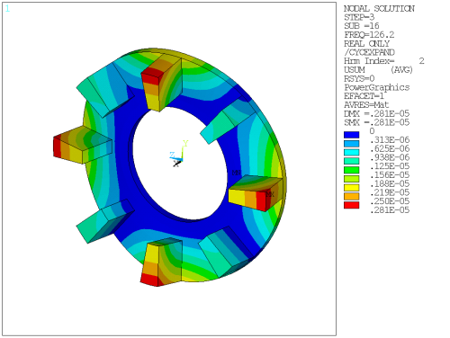
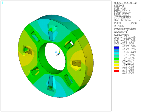
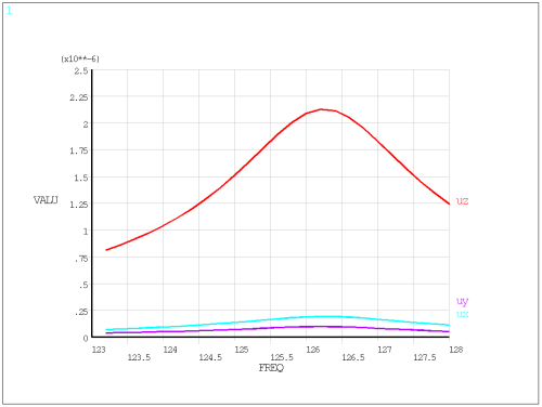
The analysis results are shown below.


