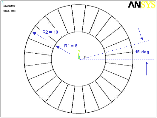
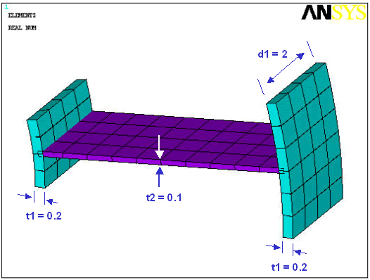
This example modal cyclic symmetry analysis presents a simplified ring-strut-ring structure used in many rotating-machinery applications.
The component is a simplified fan inlet case for a military aircraft engine. As part of the design process for the assembly, you must determine the vibration characteristics (natural frequencies and mode shapes) of the inlet case.
The geometric properties for this analysis are as follows:


The material properties for this analysis are as follows:
| Young's modulus (E) = 10e6 |
| Poisson's ratio (υ) = 0.3 |
| Density = 1e-4 |
All applicable degrees of freedom are used for the cyclic symmetry edge-component pairs. The first six mode shapes for all applicable harmonic indices are requested.
Use this input file (named cyc_symm.inp) to perform the example modal cyclic symmetry analysis. The file contains the complete geometry, material properties and solution options for the finite element model.
! Modal Cyclic Symmetry Analysis Example
! Ring-Strut-Ring Configuration

! STEP #1
! Start an interactive session

! STEP #2
! Read in this input file: cyc_symm.inp

finish
/clear

r1=5
r2=10
d1=2
nsect=24
alpha_deg=360/nsect
alpha_rad=2*acos(-1)/nsect

/view,1,1,1,2
/plopts,minm,0
/plopts,date,0
/pnum,real,1
/number,1

/prep7
csys,1
k,1,0,0,0
k,2,0,0,d1
k,3,r1,0,0
k,4,r1,0,d1
l,3,4
arotat,1,,,,,,1,2,alpha_deg/2
k,7,r2,0,0
k,8,r2,0,d1
l,7,8
arotat,5,,,,,,1,2,alpha_deg/2
arotat,2,,,,,,1,2,alpha_deg/2
arotat,6,,,,,,1,2,alpha_deg/2
a,5,6,10,9
mshkey,1
et,1,181
r,1,0.20
r,2,0.1
mp,ex,1,10e6
mp,prxy,1,0.3
mp,dens,1,1e-4
esize,0.5
asel,,,,1,4
aatt,,1
asel,,,,5
aatt,,2
allsel
finish

/solution
antype,modal
modopt,lanb,6
mxpand,6,,,yes
dk,5,uz,0
finish

aplot
/prep7

/eof

! STEP #3
! Configure the database for a cyclic symmetry analysis

cyclic

! STEP #4
! Mesh the areas

amesh,all

! STEP #5
! Turn on cyclic symmetry graphical expansion

/cycexpand,,on

! STEP #6
! Plot the elements

eplot

! STEP #7
! List the cyclic status

cyclic,status

! STEP #8
! List the cyclic solution option settings

cycopt,status

! STEP #9
! Solve the modal cyclic symmetry analysis

/solution
solve

! STEP #10
! Specify global cylindrical as the results coordinate system

/post1
rsys,1

! STEP #11
! Read results for "load step 1 - substep 4 - harmonic index 0"

set,2,6

! STEP #12
! Plot the tangential displacement contour

plns,u,y

! STEP #13
! Read results for "load step 13 - substep 1 - harmonic index 12"

set,13,1

! STEP #14
! Plot the tangential displacement contour

plns,u,y

! STEP #15
! Read results for "load step 2 - substep 5 - harmonic index 1"

set,2,5

! STEP #16
! Plot the tangential displacement contour

plns,u,y
The following table describes the input listing and the steps involved in the example modal cyclic symmetry analysis in more detail.
| Step | Description | Command |
|---|---|---|
| 1. |
Start an interactive session. |
--- |
| 2. |
Read the input file: cyc_symm.inp | /INPUT,CYC_SYMM.INP |
| 3. |
Specify a cyclic symmetry analysis and configure the database accordingly. | CYCLIC |
| 4. |
Mesh the areas. | AMESH,ALL |
| 5. |
Activate cyclic symmetry graphical expansion. | /CYCEXPAND,,ON |
| 6. |
Plot the elements. | EPLOT |
| 7. |
List the cyclic status. | CYCLIC,STATUS |
| 8. |
List the cyclic solution option settings. | CYCOPT,STATUS |
| 9. |
Solve the modal cyclic symmetry analysis. | |
| 10. |
Specify the global cylindrical coordinate system. | |
| 11. |
Read results for "load step 1 - substep 4 - harmonic index 0." | SET,2,6 |
| 12. |
Plot the tangential displacement contour. Executing this step causes the struts of the assembly to bend "in phase." | PLNSOL,U,Y |
| 13. | Read results for "load step 13 - substep 1 - harmonic index 12." | SET,13,1 |
| 14. |
Plot the tangential displacement contour. Executing this step causes the struts of the assembly to bend "out of phase." | PLNSOL,U,Y |
| 15. |
Read results for "load step 2 - substep 5 - harmonic index 1." | SET,2,5 |
| 16. |
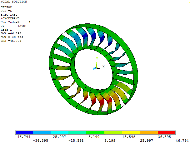
Plot the tangential displacement contour. ---- This step completes the example modal cyclic symmetry analysis. Your results should match those shown in Figure 5.1: Example Modal Cyclic Symmetry Analysis Results. | PLNSOL,U,Y |
The results of your analysis should match those shown here:
Note: Mode shape values may vary slightly depending on your computer system.
To view a traveling wave animation of your model, issue the ANCYC,24,,0.1 command. For more information, see Applying a Traveling Wave Animation to the Cyclic Model.


