


The material, initial velocity, geometry and options for analysis can be modified from the properties dialog of a solid body as shown in the figures below. Material parameters such as the body type and mass properties are defined as shown in the following table and figure for the Material tab.
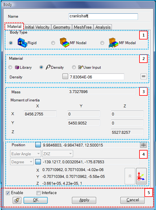
Figure 3.17: Description of Material parameters in the of Solid Body properties dialog
| Parameter | Symbol | Description | Dimension (Range) |
| 1. Body Type | N/A | Use to select the type of body. When the type is set to , the body will be treated as a rigid body. When the type is , the body will be treated as a Nodal EasyFlex Body. When the type is , the body will be treated as a Modal EasyFlex Body. | N/A |
| 2. Material | N/A |
Use to select the material type for calculating the mass properties of the body. When the type is set to , the material can be selected from the pre-defined Materials. When the type is , the mass properties are calculated from the user-specified density value. When the type is , the mass properties such as mass, mass moment of inertia, the center of mass and orientation can be defined directly. When or body types are selected, only the material type is available. |
For Density: Mass/ Length^3 (Real≥0) For others: N/A |
| 3. Mass Properties |  , , | Use to display the mass and moment of inertia which are automatically calculated for the material type and from equations Equation 8–72 and Equation 8–73 in General Formulation for Material. Also used to set the mass and moment of inertia for the material type. |
For Mass: Mass (Real>0) For Moment of Inertia: Mass*Length^2 (Real) |
| 4. Position… |  , , | Use to set the position and orientation of the body reference frame when
the Material type is set to
. The position can be
defined by direct entry or by using the point picker. The
orientation can be calculated by defining the angle type as
or
and specifying the rotational
sequence, such as ZXZ or
XYZ. For more information, see Marker Properties. |
For Position: Length (Real) For Angle: Degrees or Radians (Real) |
| 5. Control buttons | N/A | If all necessary parameters are set, these buttons are enabled. For more information about the control buttons, refer to Entity Properties Access and Modification. | N/A |
Parameters for initial velocity are defined as shown in the table and figure below.
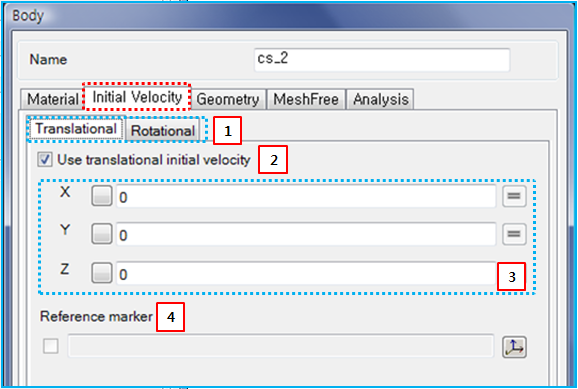
Figure 3.19: Description of Initial Velocity parameters in the Solid Body properties dialog
| Parameter | Symbol | Description | Dimension (Range) |
| 1. Translational / Rotational | N/A | Use to select either Translational or Rotational direction parameters for the initial velocity. | N/A |
| 2. Use… | N/A | Use to enable section 3. When this option is selected, the parameters in section 3 are activated. | N/A |
| 3. X, Y, Z |  , , |
Use to set the user-specified initial velocities for the translational and rotational degrees of freedom. When the reference marker in section 4 is not defined, the defined values refer to the velocities of the body reference frame in Equation 3–3 and Equation 3–4 as follows.
|
For Translational: Length/Time (Real) For Rotational: Radians/Time (Real) |
| 4. Reference marker |
|
Use to set the reference marker using the General Picker. When this marker is defined, the initial velocities of the body reference frame are calculated from the user-specified velocities as follows:
where,
| N/A |


Geometry parameters are defined as shown in the table and figure below.
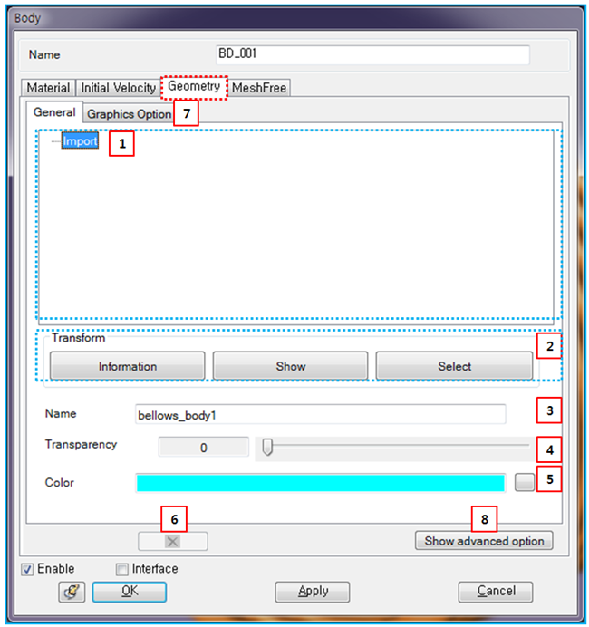
Figure 3.21: Description of Geometry parameters in the Solid Body properties dialog
| Parameter | Symbol | Description | Dimension (Range) |
| 1. Hierarchy of geometry | N/A | Used to display the hierarchy of the body geometries and shows the properties of the selected geometry. Import means that the geometry was created by importing from CAD . If the geometry is a result of a Boolean or Split function, the Boolean or Split keyword is instead displayed to represent the geometry hierarchy. | N/A |
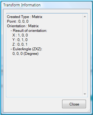
| 2. Transform | N/A | Use to display or set the geometry reference frame for the imported geometry. shows the origin and orientation of the geometry reference frame as shown in Figure 3.22: Transform Information for the geometry. displays the reference frame on the screen. sets the reference frame by using the Transform Picker. | N/A |
| 3. Name | N/A | Use to define the name of the geometry. The name is used to replace the geometry with a new geometry when using Replace CAD Geometry. This option is available for geometries created from CAD. | N/A |
| 4. Transparency | N/A | Use to set the transparency of all geometries in the body by using either the scroll control or direct entry. As this value is increased, the transparency of the body increases. | N/A |
| 5. Color | N/A | Use to set the color of all geometries in the body by using the color table. | N/A |
| 6. Deletion | N/A | Use to delete the selected geometry from the geometry hierarchy. Since a body must always have at least one geometry, this option is only activated under conditions where deletion is possible. | N/A |
| 7. Graphics Option | N/A | Use to set the parameters to control the facet size for graphics visualization quality in pre and post-processing. By clicking the button, you can control the faceting parameters for geometry precision. If Use Default Values is selected, the program default values are used for the faceting parameters. When this option is cleared, you can set the values manually. For more information about faceting parameters, see Geometry faceting in Faceset properties. | |
| 8. Show/Hide Advanced Option | N/A | Use to show or hide the Advance tab in the body properties dialog (see below). | N/A |
Parameters on the Advance tab are defined in the table and figure below.
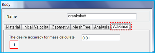
Figure 3.24: Description of Advance parameters in the Solid Body properties dialog
| Parameter | Symbol | Description | Dimension (Range) |
| 1. The desire accuracy… | N/A | Use to set the accuracy required when the kernel calculates the mass properties. If this value is small, the accuracy of the mass properties increases but calculation time may also be increased and the process may fail due to tight tolerances. |
Length (Real>0) |
In the EasyFlex and Analysis tabs, parameters for the nodal EasyFlex body can be defined. The parameters will be introduced in Nodal EasyFlex Body Properties.