


Properties and options for analysis can be modified from the solid body properties dialog in a subsystem or part, as shown in the figures below. The material, initial velocity and geometry properties have been introduced in Solid Body Properties. This section explains the EasyFlex and Analysis properties, as defined in the figure below and in the following table.
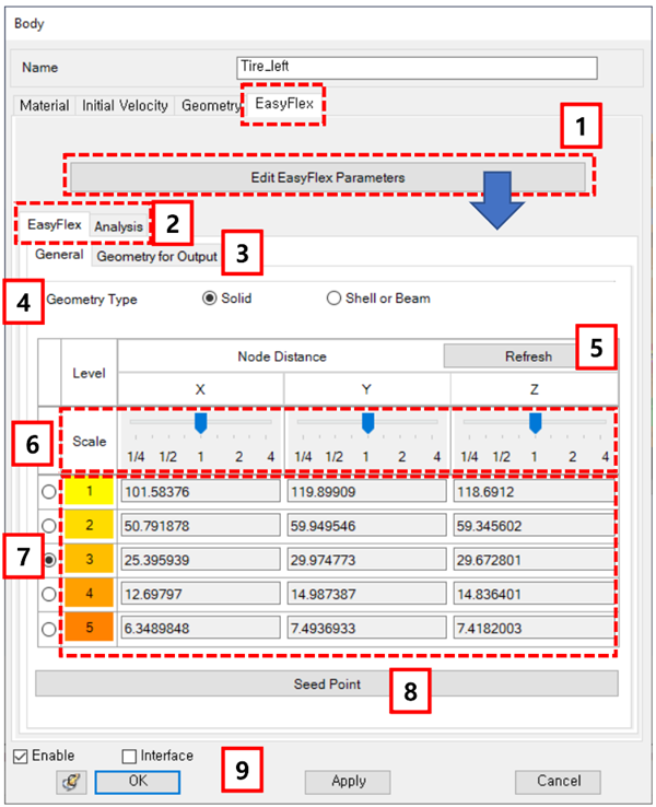
Figure 3.190: Description of EasyFlex parameters in the Solid Body properties dialog
| Parameter | Symbol | Description | Dimension (Range) |
| 1. Edit… | N/A | Use to display the parameters for the nodal EasyFlex body. | N/A |
| 2. EasyFlex/Analysis | N/A | Use to display the Nodal EasyFlex Body Properties. | N/A |
| 3. Geometry for Output | N/A | Use to display the parameters for geometry faceting as shown in Nodal EasyFlex Body Properties. Nodes which consist of triangular facets are used to report stress, strain and deformation of the flexible body during post processing. The default Maximum Facet Size is same as the node distance in level 4 (see Level below). If the size of result file is too large, it can be reduced by a using larger value than the default value. | N/A |
| 4. Geometry Type | N/A | Use to set the geometry type. When Solid type is selected, the solver will treat the stiffness as being slightly harder. When the Shell or Beam type is selected, the solver will treat the stiffness as being slightly softer. | N/A |
| 5. Refresh | N/A | Use to recalculate the node distance when the body is rotated or its geometry is changed. When the geometry is changed or a model from an earlier version than 5.1 is opened, the node distance must be refreshed. | N/A |
| 6. Scale | N/A | Use to change the node distance with a slider bar for each component. The new node distance is calculated by multiplying the value of the slider bar by the original node distance. | N/A |
| 7. Level | N/A | Use to set the node distance used in the solver. This value effects the number of nodes, which determines the accuracy of the stiffness and mass matrices. You can simultaneously select two levels, at which point local refinement is activated. For eigenvalue analysis, only the higher level is used for the solver. | N/A |
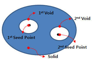
| 8. Seed Point | N/A |
Use to set the seed point for the void geometry as shown in the figure below. A solid geometry can sometimes have a void internally and the solver requires the seed point to recognize that void. The seed point can be defined as any point inside the void. When the solid geometry has several voids, you must define a corresponding seed point for each void as shown in the figure below.
| N/A |
| 9. OK… | N/A | Use to close this dialog, either saving the changed parameters or without saving. | N/A |
Parameters for geometry output are defined in the figure below and in the following table.
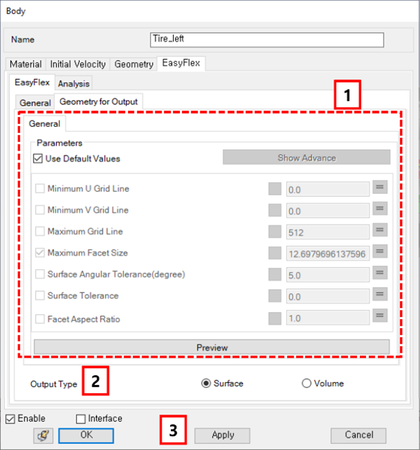
Figure 3.192: Description of the Geometry for Output dialog for an EasyFlex body
| Parameter | Symbol | Description | Dimension (Range) |
| 1. General | N/A | Use to set the parameters to control the facet size for postprocessing. For more information about faceting, see Figure 3.65: Parameters in the Faceset properties dialog. | N/A |
| 2. Output Type | N/A | Use to set the geometry type for output. When Surface is selected, triangular patches on the surface of the EasyFlex body will be generated for the postprocessor. When Volume is selected, tetra elements will be generated for the postprocessor. Though this option may often cause a failure, it is useful for analysis of stress or strain on a cross section. | N/A |
| 3. OK… | N/A | Close this dialog with or without saving the changed parameters. | N/A |
Analysis parameters are defined as shown in the figure below and in the following table.
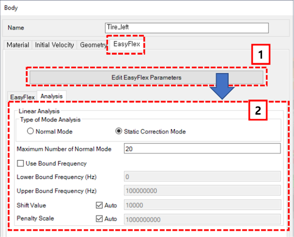
Figure 3.194: Description of Analysis parameters in the Solid Body properties dialog
| Parameter | Symbol | Description | Dimension (Range) |
| 1. Edit… | N/A | Use to display the parameters for analysis of the nodal EasyFlex body. | N/A |
| 2. Linear… | N/A | Use to set the parameters for body eigenvalue analysis. See Body Eigenvalue Analysis Properties. | N/A |