


From the Faceset properties dialog, the parameters for the contact surface and connector can be modified as shown in the figure below. The list of faces is only available for a connector. The other parameters are used to define the contact surface. Parameters for the Faceset are defined in the following table.
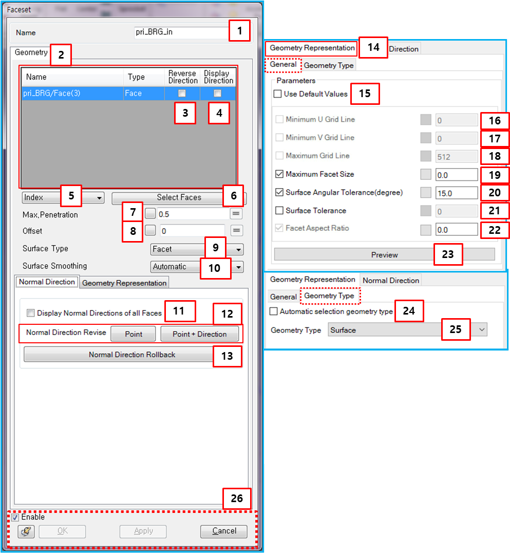
Figure 3.65: Parameters in the Faceset properties dialog
| Parameter | Symbol | Description | Dimension (Range) |
| 1. Name | N/A | Use to set the name of the Faceset. | N/A |
| 2. List of Faces | N/A | Used to display the names, types and normal directions of the selected faces. The names are not editable and the face type is only available for the contact surface. | N/A |
| 3. Reverse Direction | N/A | Use to reverse the normal direction of the selected face. | N/A |
| 4. Display Direction | N/A | Use to display the normal direction of the selected face on the screen. The normal direction can be set through parameters 3, 11 and 12. The two normal directions of the base and action contact surfaces in the contact entity must be facing each other for the contact to work. | N/A |
| 5. Index/Color | N/A | Use to set a method for selecting faces which belong to the Faceset. When the geometry is replaced, a new Faceset in the replaced geometry can be automatically created using this option and all connectors such as joint, force and contact are automatically modeled with new Faceset. When the Index option is used, faces for new Faceset are selected with the faces which are matched to the indexes of the original faces. When the Color option is used, faces for new Faceset are selected according to the color of the original faces. For replacing the geometry, see Replace CAD Geometry. | N/A |
| 6. Select Faces | N/A | Use to add or remove faces for the contact or connector using the MultiFace Picker or Color Face Picker. When the selection method (above) is set to Index, MultiFace Picker is used to select faces. When the method is set to , the Color Face Picker is used to select faces. | N/A |
| 7. Max. Penetration |

| Use to set the maximum penetration. For more information, see Maximum Penetration for contact geometry in the Motion Theory Reference. |
Length (Real>0) |
| 8. Offset |

| Use to set the offset of the contact surface. For more information, see Contact case with Offset in the Motion Theory Reference. |
Length (Real≥0) |
| 9. Surface Type | N/A | Use to set the type of the contact surface, such as or . For more information, see Faceset. | N/A |
| 10. Surface Smoothing | N/A | Use to set the smoothing type to or . This option is available when the surface type is set to . For more information, see Smoothing and No Smoothing geometries in the Motion Theory Reference. | N/A |
| 11. Display Normal Directions… | N/A | Use to display the normal directions of all faces in the Faceset. | N/A |
| 12. Normal Direction… | N/A | Use to change the normal directions of all faces in the Faceset. There are two methods; and . For more information, see Normal direction changes with Point function in the Motion Theory Reference. | N/A |
| 13. Normal Direction Rollback | N/A | Use to revert the normal directions of all faces in the Faceset to their original directions. | N/A |
| 14. Geometry Representation | N/A | Use to set the facet size of faces in the Faceset. There are three parameters as described below (16 to 26). | N/A |
| 15. Use Default Values | N/A | Use the program default values for faceting. | N/A |
| 16. Minimum U Grid Line | N/A | (Read Only) The minimum number of vertices in the U direction of the face. |
N/A (Integer>0) |
| 17. Minimum V Grid Line | N/A | (Read Only) The minimum number of vertices in the V direction of the face. |
N/A (Integer>0) |
| 18. Maximum Grid Line | N/A | (Read Only) The maximum number of facets. For precise surface representation, a greater value than the default is recommended. |
N/A (Integer>0) |
| 19. Maximum Facet Size |

| Use to set the maximum facet size. For more information, see Facet Size Control. |
Length (Real>0) |
| 20. Surface Angular Tolerance |

| Use to set the surface angular tolerance. For more information, see Facet Size Control. |
Angle (Degree>0) |
| 21. Surface Tolerance |

| Use to set the surface tolerance. For more information, see Facet Size Control |
Length (Real>0) |
| 22. Facet Aspect Ratio | N/A | (Read Only) The facet aspect ratio. For more information, see Facet Size Control. |
N/A (Real>0) |
| 23. Preview | N/A | Use to display the facets of the Faceset on the screen. If you close the dialog, the preview will be hidden. | N/A |
| 24. Automatic selection geometry type | N/A | Use to set the geometry type automatically. When this option is selected, the geometry type is set to when the body is a sphere defined as a radius and center point, not as an imported CAD file. Otherwise, is set. | N/A |
| 25. Geometry type | N/A |
Use to set a surface geometry type to or . When is selected, the detection method for contact and the identifcation method for contact points is used as shown in Contact Detection and Method for Finding Exact Contact Point Position in the Motion Theory Reference, respectively. When is selected, the detection method for contact and the identification method for contact points is used as shown in ???? and Multi-Curve to Multi-Curve Contact in the Motion Theory Reference, respectively. | N/A |
| 26. Control buttons | N/A | If all necessary parameters are set, these buttons are enabled. For more information about the control buttons, refer to Entity Properties Access and Modification. | N/A |