In this example problem, an ACP (Pre) component system is used to specify the layered composite material of the ring and nozzle as well as several aspects of the model as described in this section. All modeling, material, and composite specification data is imported to the downstream thermal and structural analyses through connections in Workbench.
This section demonstrates the following modeling specifications:
- 29.4.1. Insert ACP (Pre) and define a custom material in Workbench
- 29.4.2. Specify Modeling Details in Mechanical
- 29.4.3. Specify Composite Layers in ACP
- 29.4.4. Transfer Modeling and Composite Specifications to Downstream Thermal and Structural Analyses in Workbench
- 29.4.5. View the Transferred Composite Layers in Mechanical
Steps to include an ACP (Pre) component system and define a custom material for the nozzle and ring assembly are described below.
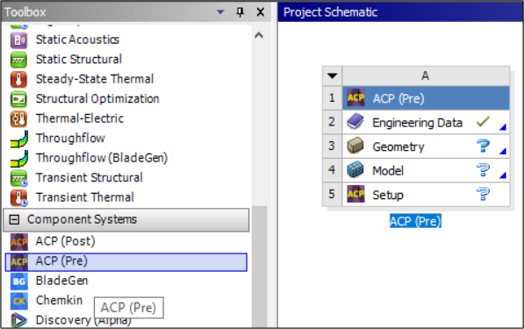
Insert the ACP (Pre) component system by dragging it from the Toolbox to the Project Schematic in Workbench.
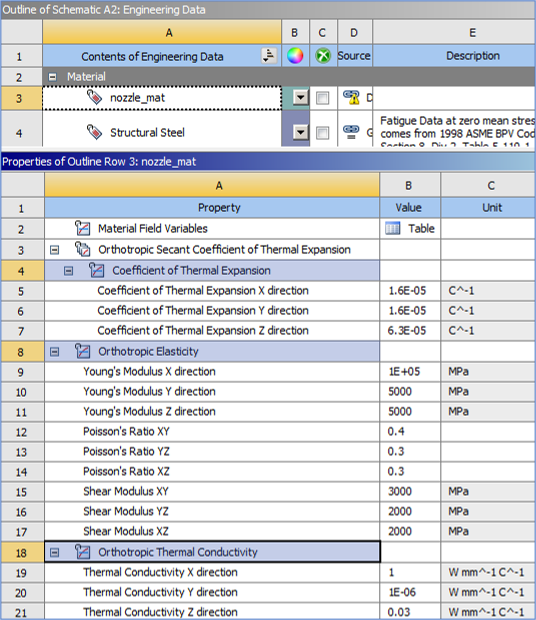
Open the Engineering Data tab by double-clicking the Engineering Data cell, and define a custom material named "nozzle_mat" with following details:
Close Engineering Data tab and import the shared geometry.
Start Mechanical by double-clicking the Model cell of the ACP (Pre) system. Within Mechanical, specify the various aspects of the model as detailed below.
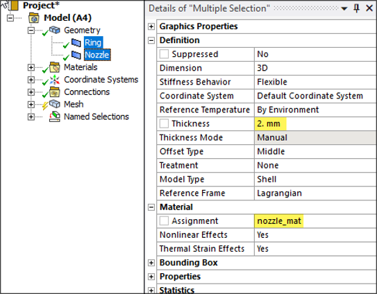
Specify Thickness as 2 mm and assign material for Ring and Nozzle in Geometry as seen below.
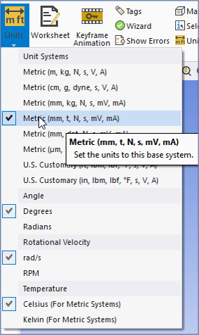
Set the units as shown below.
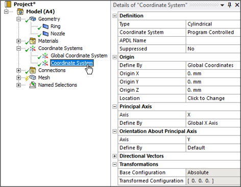
Create a cylindrical coordinate system with following details:
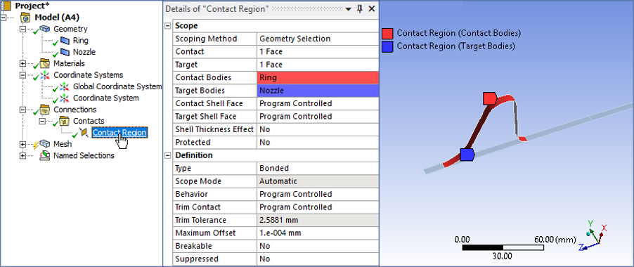
The following figure shows the details of the Bonded contact region between the ring and nozzle.
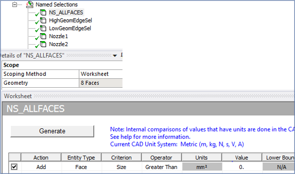
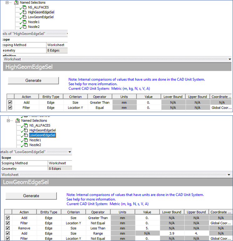
Define named selections. See the details of three named selections below: NS_AllFaces, HighGeomEdgeSel, LowGeomEdgeSel.
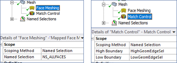
Specify the mesh using Face Meshing scoped to the named selection NS_ALLFACES and Match Control scoping the High and Low Boundaries to the named selections HighGeomEdgeSel and LowGeomEdgeSel, respectively, as shown below. Then generate the mesh.
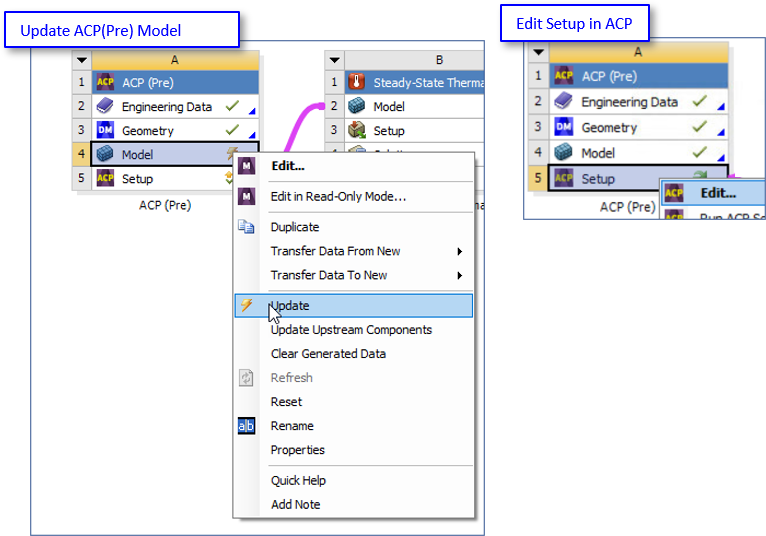
Close Mechanical and update the Model cell of the ACP (Pre) system in Workbench by right-clicking it and selecting (see Update ACP(Pre) Model in the figure below). When Model has finished updating, you will see a green check. Then open Ansys Composite PrepPost by right-clicking the Setup cell of the ACP (Pre) system and choosing (see Edit Setup in ACP in the figure below).
Within Ansys Composite PrepPost, follow the steps listed below to generate composite layers:
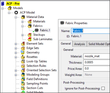
Create "Fabric.1" with the specified properties shown in the following figure. From the tree, right-click Fabrics, select from the drop-down menu, assign the Fabric Properties shown in the figure, and click then .
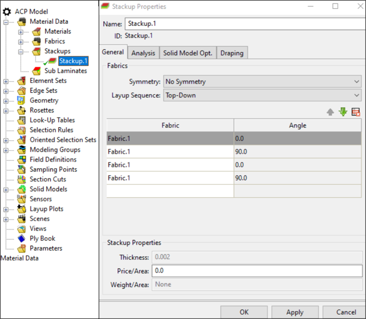
Create "Stackup.1" with the specified properties shown in the following figure. From the tree, right-click Stackups, select from the drop-down menu, assign the Stackup Properties shown in the figure, and click then .
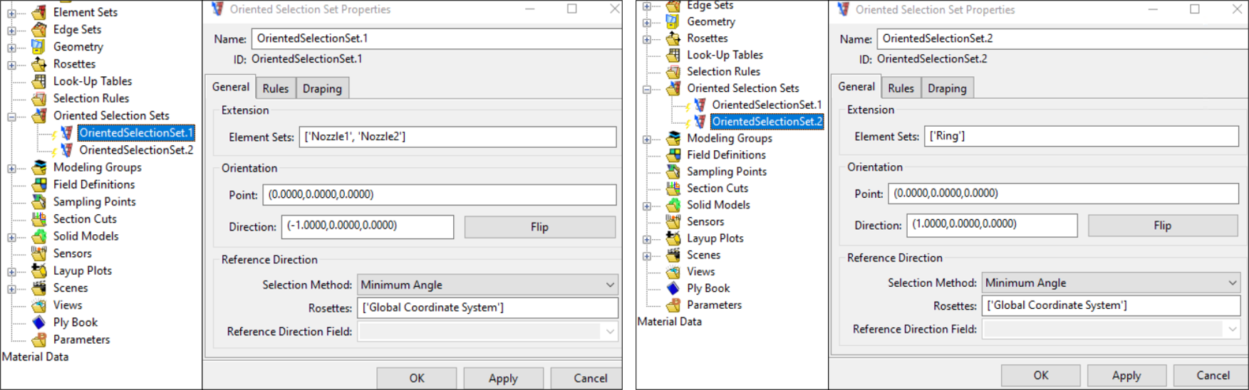
Create "OrientedSelectionSet.1" and "OrientedSelectionSet.2" as shown in the following figure. For each, right-click Oriented Selection Sets, select from the drop-down menu, assign the Oriented Selection Set Properties shown in the figure, and click then .
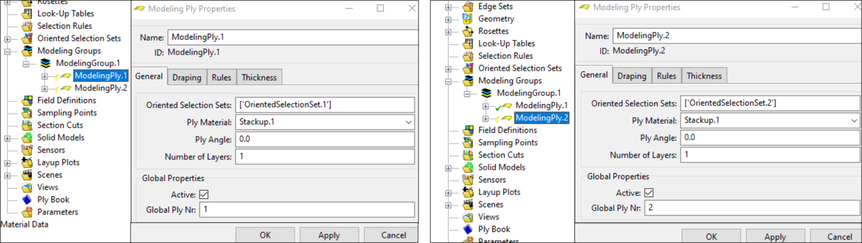
Create "ModelingPly.1" and "ModelingPly.2" as shown in the following figure. First create "ModelingGroup.1" by right-clicking Modeling Groups, selecting from the drop-down menu, and clicking . Then for each ply, right-click , select from the drop-down menu, assign the Ply Properties shown in the figure, and click then .
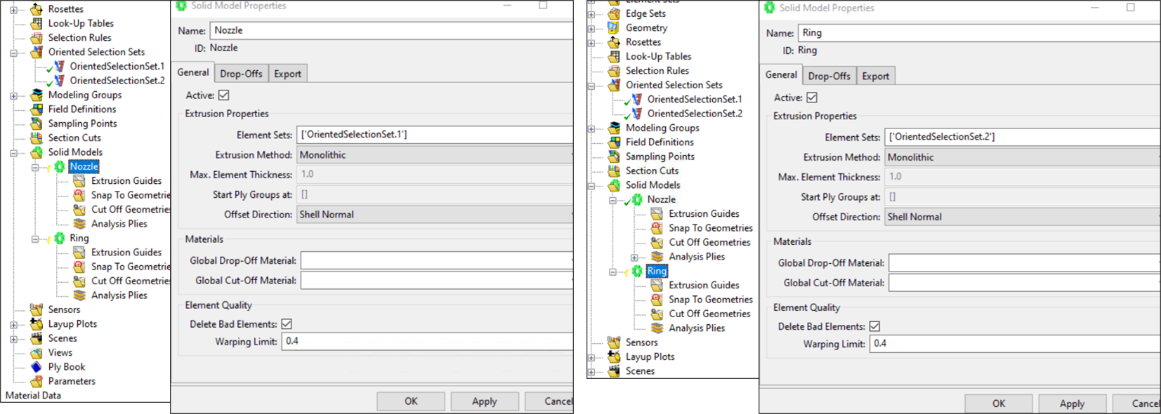
Create solid models, "Nozzle" and "Ring", as shown in the following figure. For each ply, right-click , select from the drop-down menu, assign the Solid Model Properties shown in the figure, and click then .
Close ACP and update the Setup cell of the ACP (Pre) system in Workbench (right-click Setup and choose Update from the drop-down menu). This completes the setup of ACP for generating composite layers.
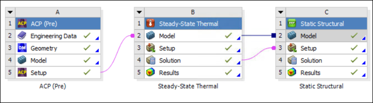
Set up the rest of the analysis by dragging a Steady-State Thermal system followed by a Static Structural system from the Toolbox to the Project Schematic in Workbench with the connections and data transfer shown below.
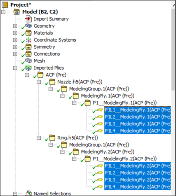
Start Mechanical from the thermal or structural analysis by double clicking their Setup cell and verify that the plies defining the composite material of the ring and nozzle are properly transferred as Imported Plies in Mechanical as shown below.