


The following properties are needed for a Modeling Ply definition:
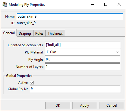
Name: Name of the Modeling Ply.
Oriented Selection Sets: Defines the offset and material direction.
Material: Modeling Ply Material (Fabric, Stackup or Sublaminate).
Ply Angle: The design angle between the reference direction and the ply fiber direction.
Number of Layers: Number of times the plies are generated.
Active: Active plies are considered in an analysis, inactive plies are present but not considered.
Global Ply Nr: Defines the global ply order. Per default a new Modeling Ply is added after the last Modeling Ply of the Modeling Group. The order of the Modeling Plies in the Modeling Groups is equal to this value.
Consider the draping effects during the production process in the lay-up definition. The draping approach can be specified in the Draping tab of the Modeling Ply Properties dialog. The following types of draping are available:
No Draping (default)
Internal Draping: The draped fiber directions are determined by the internal ACP draping algorithm.
Tabular Values: Draped fiber directions are interpolated from a Look-Up Table.
The parameters for Internal Draping and Tabular Values are explained below.
Note: Draping can also be assigned to an Oriented Selection Set (OSS). In this case, the Reference Direction of the OSS is adjusted. All associated modeling plies use this draped reference direction. This avoids running multiple draping simulations on the same surface. If is applied to a modeling ply associated with a draped OSS, then an independent draping simulation is started for the Modeling Ply.
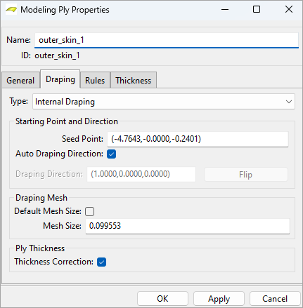
Internal Draping
The following parameters control the :
Seed Point: Starting point of the draping process.
Draping Direction: Sets the primary draping direction for the draping scheme. The secondary direction is always orthogonal to the primary.
Auto Draping Direction: Uses fiber direction of the production ply.
User-Defined Direction: Uses the defined vector.
Default Mesh Size: Enable this property to use the default size for the draping mesh. The default size is the average element size of the shell mesh.
Mesh Size: A user-defined mesh size for the draping mesh can be set if Default Mesh Size is disabled.
Thickness Correction: The thickness of the draped ply is corrected based on the shearing (see Thickness Correction).
For more information on the Draping feature, see Draping Algorithm and its Limitations.
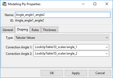
Tabular Values
The tabular value draping options lets you choose the draped fiber directions from vectors in a Look-Up Table:
Correction Angle 1: Sets the draped fiber direction.
Correction Angle 2: Sets the draped transverse direction.
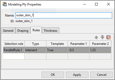
Like in the definition of an Oriented Selection Set, a Modeling Ply can have one or more Selection Rules. The combination of all Element Sets and active Selection Rules defines the extension of the Modeling Ply. Each rule has its own Boolean operator (intersect, add, or remove) which allows you to define arbitrary combinations of rules (see Boolean Operation Types).
Template Rules
In addition, the Selection Rule parameters can be redefined in the Modeling Ply definition. This prevents the same Selection Rule from being defined multiple times and allows staggering to be defined with a single Selection Rule. In the Rules tab, activate Template as True for those selection rules that have to be treated as template rule and set the values.
The template parameters for each selection rule type are given in the table below:
| Rule Type | Parameter 1 | Parameter 2 |
|---|---|---|
| Parallel Selection Rule | Lower Limit | Upper Limit |
| Tube Selection Rule | Outer Radius | Inner Radius |
| Cylindrical Selection Rule | Radius | - |
| Spherical Selection Rule | Radius | - |
| Cut-Off Selection Rule | - | - |
| Geometrical Selection Rule (Geometry) | In-plane capture tolerance | - |
| Variable Offset Rule | - | - |
| Boolean Selection Rule | - | - |
The thickness of the ply is defined by default by the thickness of the ply material.
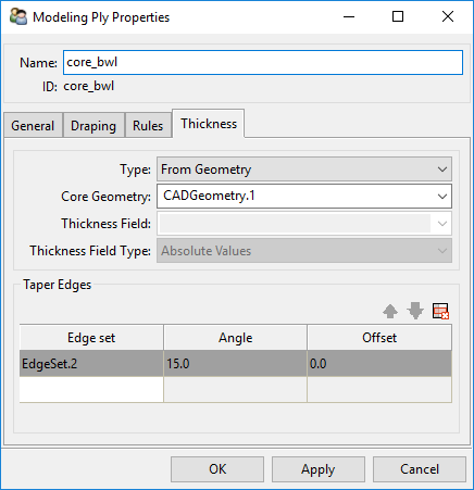
For Fabrics the ply thickness can also be defined by a CAD Geometry or Tabular Values. The thickness options are:
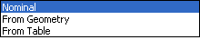
Type: Thickness definition method.
Nominal: The thickness defined in Fabrics is used for the thickness definition.
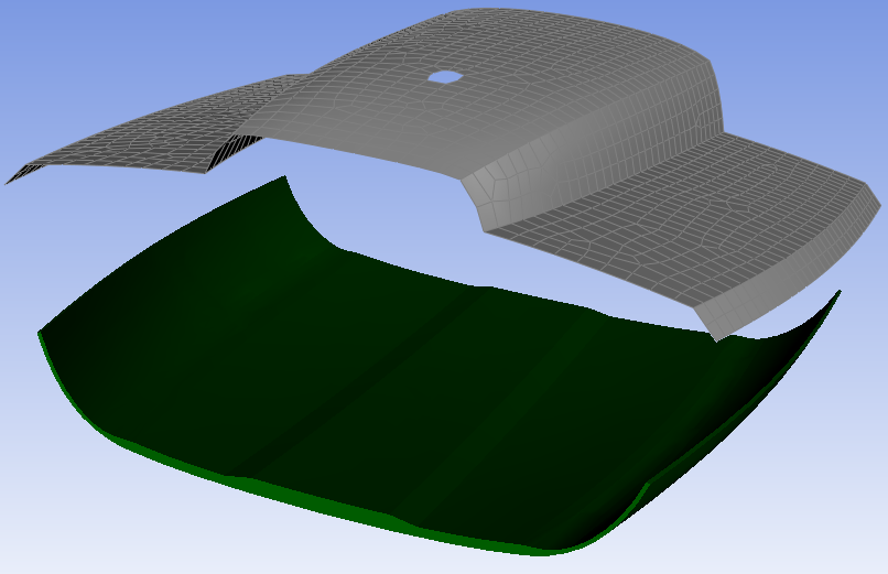
From Geometry: CAD Geometry calculates the thickness. In the case of a complex core ply, it can be helpful to work with a CAD Geometry defining the thickness distribution of the core. ACP samples through the CAD Geometry for each element and maps the thickness. The thickness is evaluated in the element normal direction.
From Table: A data field evaluates the thickness. ACP inter- or extrapolates the thicknesses for each element. One data point contains the global coordinates and the thickness values. The values in the table can be used as absolute or relative thickness. See Look-Up Tables for more information on how to define this table.
Core Geometry: Thickness of the CAD geometry is mapped to the mesh.
Thickness Field: Thickness is determined by mapping a value field to the mesh.
Thickness Field Type:
Absolute Values: Values in the Look-Up Table define the thickness.
Relative Scaling Values: Values in the Look-Up Table are scaling factors.
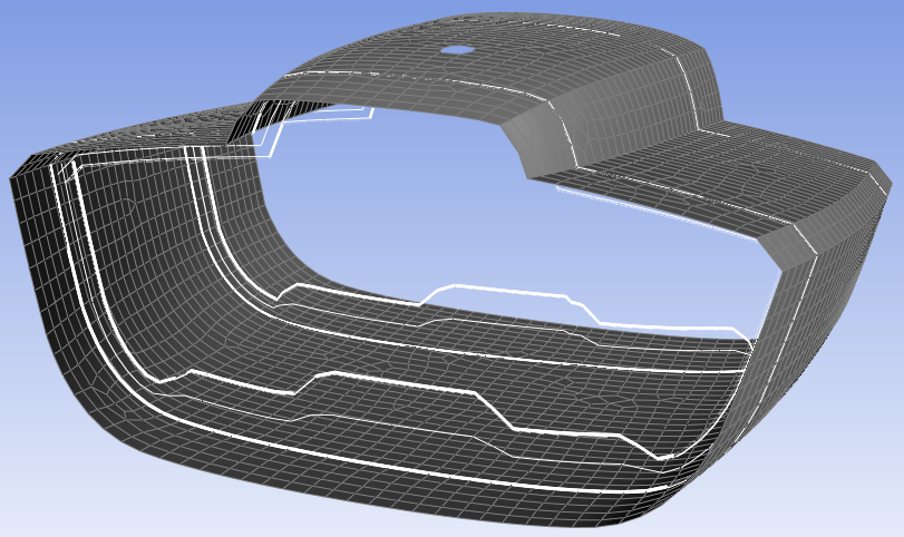
Taper Edges: adds an edge tapering to the selected Edge Set.
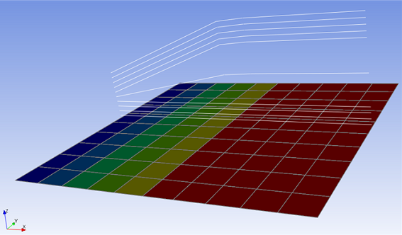
Core plies are commonly tapered along the boundary. The Taper Edges option allows you to define a taper angle and a taper offset for each edge. The figure below shows a 15 degree tapering along the edge on the left. The thickness is 0 at the selected edge and grows with the specified angle. The Taper Edges option is intended for applying a taper angle to a single ply, for example, a core material. When applied to multiple Modeling Plies the thickness distributions of all plies are superposed. For more information, see Edge Tapering and Tapering of Multiple Plies.
By default, ACP analyzes ply tapering at the element centers. Each element is cropped from the ply if the ply thickness at the element center is negative. This binary representation may not be sufficiently accurate in certain cases. If the Use Nodal Thickness is enabled, the ply tapering will be refined, which results in a more accurate model. For more information, see Element- vs. Node-based Thicknesses.
The context menu for Modeling Ply has the following options:
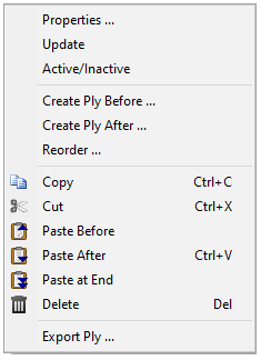
Properties: Display the Modeling Ply Properties dialog.
Update: Updates the selected Modeling Ply.
Active/Inactive: Activate or deactivate the selected Modeling Ply. Inactive plies are defined in the database but not considered in the analysis.
Create Ply Before: Create a new ply before the selected one.
Create Ply After: Create a new ply after the selected one.
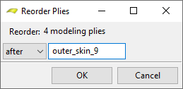
Reorder: Move the selected Modeling Ply (or plies if several are selected) before or after another defined ply.
Copy: Copy the selected Modeling Plies to the clipboard.
Paste at End: Paste Modeling Plies from the clipboard to the end of the selected Modeling Group.
Paste Before: Paste Modeling Plies from the clipboard before the selected ply.
Paste After: Paste Modeling Plies from the clipboard after the selected ply.
Delete: Delete the selected Modeling Plies.
