The Solid Model feature creates a layered solid element model from a composite shell model. The solid element model can be integrated into a Workbench workflow or exported for use outside of Workbench. Analysis of a Composite Solid Model explains the Solid Model workflow in Workbench, and Guide to Solid Modeling provides general information on solid modeling.
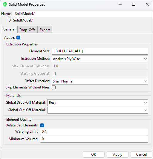
The settings for the solid model generation are adjusted under the Solid Model context menu item Properties. The Solid Model Properties dialog covers what Element Sets are extruded, the extrusion method, Drop-Off elements handling and numbering offsets, among other things.
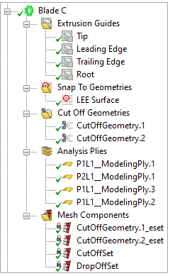
You can use Extrusion Guides, Snap-To, and Cut-Off Geometries to shape the Solid Model as desired. They are specified in the respective subfolders in the Solid Model Tree View. The Analysis Plies sub-folder shows which plies are incorporated in the Solid Model. The sub-folder Mesh Components contains internal Element Sets which are created during the extrusion.
Subtopics:
The Solid Model Properties dialog is divided into the following tabs:
The General tab has the following properties:
- Element Sets
Starting with a shell model and the lay-up definition, the shell elements are extruded to a layered solid element model. Select an Element Set to define the region of the extrusion.
Important: The mid-offset option of Element Sets is not supported for Solid Model extrusion. The ply definition must be defined without this option to obtain the correct solid model position.
- Extrusion Properties
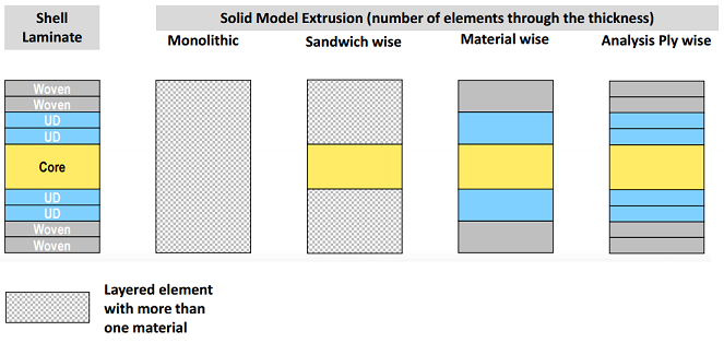
The lay-up extrusion can be organized in different ways to merge plies with different criteria:
Extrusion Method:
Analysis Ply Wise: Extrude each Analysis Ply as one solid element layer.
Material Wise: All sequential plies containing the same material are grouped in one solid element layer. A maximum element thickness can be specified that will subdivide the single element layers if necessary.
Modeling Ply Wise: Extrude each Modeling Ply as one solid element layer (for example, every Stackup or Sublaminate is extruded as one solid element layer).
Monolithic: Extrude the whole lay-up in one solid element layer.
Production Ply Wise: Extrude each Production Ply as one solid element layer if possible. Depending on the model topology, monolithic Modeling Groups may be split in order to ensure the cohesion of the resulting solid model.
Specify Thickness: Plies are grouped by iterating through the laminate from the inside out..
User Defined: Plies are grouped by iterating through the laminate from the inside out.
Sandwich Wise: Plies on either side of a core material are grouped into single element layers. The core material is extruded as one element layer.
For extrusion methods other than analysis ply-wise, see Material Handling for Different Extrusion Methods.
Max Element Thickness: Thickness at which a new Modeling Group will be introduced. If a single ply is thicker than this value it is split into layers of equal thickness no thicker than this value.
Start Ply Groups at: A new Modeling Group is introduced each time the iteration meets one of the plies specified in this option (User Defined Extrusion Method only)
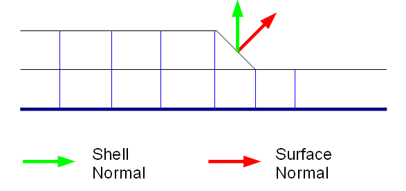
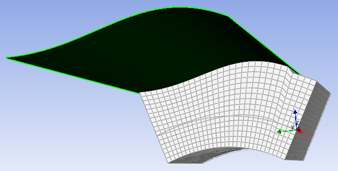
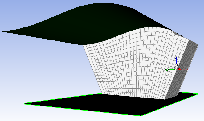
Offset Direction: With the Surface Normal option, the extrusion direction is re-evaluated after each row of solid elements. With Shell Normal option, the extrusion direction stays defined as shell normal.
An example of both options is shown in the following figure:
Figure 2.123: Offset Direction - Example
The effect is visible in the element rows above the drop-off elements. Solid Model with Surface Normal Direction 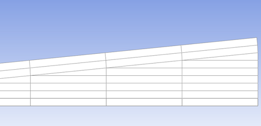
Solid Model with Shell Normal Direction 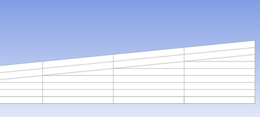
: Enable this option to automatically remove elements without plies from the region of extrusion. This ensures that no drop-off elements are created between the elements without plies and the adjacent elements. An application example is when holes are filled and meshed but do not contain a lay-up.
- Drop-Offs and Cut-Offs
The Drop-Offs and Cut-Offs section controls the global material handling for Drop-Off and Cut-Off elements in the solid model. The following options are available:
Global Drop-Off Material: This setting is used when the material handling settings for fabrics and stackups are set to Global.
Global Cut-Off Material: This setting is used when the material handling settings for fabrics and stackups are set to Global.
- Element Quality
ACP performs shape checks during the solid model generation. The checks are similar to Element Shape Testing in Mechanical APDL, and bad elements are deleted if they fail the check. You can adjust some of the limits and tolerances:
Delete Bad Elements: When enabled, ACP will perform shape checks. Disable this option to suppress the shape checks.
Warping Limit: Solid elements with a warping factor above this limit are removed from the solid model. The default value is 0.4. Twisting the top face of a unit cube by 22.5° and 45° relative to the base produces warping factors of about 0.2 and 0.4, respectively.
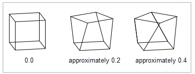
Minimum Volume: Elements with a volume equal to or smaller than this limit are deleted. The default value is 0 so only elements with a negative or zero volume are removed. You can adjust this parameter accordingly should the solver produce error messages about small elements with a volume close to zero. For instance, the Mechanical APDL solver logs this error: *** ERROR *** Zero volume in element...
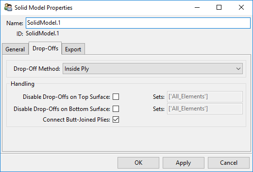
The Drop-Offs Tab has the following properties:
Drop-Off Method: Define the ply's Drop-Off before or after the edge.

Disable Drop-Offs on Top Surface: Deactivates Drop-Off elements on the top face sheet of the laminate for the selected (oriented) Element Sets.
Disable Drop-Offs on Bottom Surface: Deactivates Drop-Off elements on the bottom face sheet of the laminate for the selected (oriented) Element Sets.
Figure 2.125: Disable Drop-Offs
Disable Drop-Offs option deactivated 
Disable Drop-Offs option activated 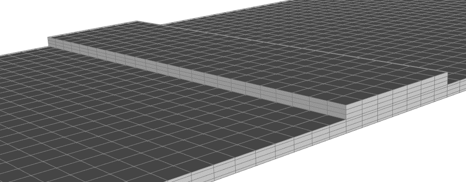
Connect Butt-Joined Plies: If a composite layer ends away from a mesh boundary, it tails off with a Drop-Off Element. These Drop-Off elements are degenerated brick elements that are reduced from bricks into prisms. This option can prevent an element Drop-Off of two adjacent, sequential plies in the same modeling group. By default, it is active.
The feature is limited to plies that appear sequentially in the same Modeling Group. It is not possible to connect all butt-jointed plies that are arranged in a circle. This is a known limitation.
An example of a sandwich structure with divided core material is shown below to demonstrate the use of a ply connection.
Figure 2.126: Connect Butt-Jointed Plies
Connect Butt-Joined Plies activated 
Connect Butt-Joined Plies deactivated 
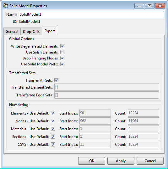
The Export Tab has the following properties:
- Global Options
Write Degenerated Elements: Include Drop-Off elements and Cut-Off elements in the solid model export. Deactivating this option can lead to holes in the mesh and prevent import into Mechanical. Deactivating this option is not advised during a Workbench workflow.
Figure 2.128: Write Degenerated Elements
Export with Drop-Off Elements 
Export without Drop-Off Elements 
Use SOLSH Elements: Create the model with Solid-Shell elements (SOLSH190).
Drop Hanging Nodes: Remove hanging nodes from model before solve (default on).
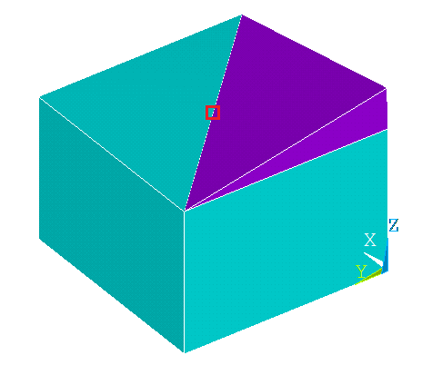
Hanging nodes are not connected to all the neighboring elements. Hanging nodes can occur when quadratic hexahedral, tetrahedral, and prism elements are connected together. Hanging nodes can lead to discontinuous deformation fields and are therefore not desirable. When this option is active, element edges containing a hanging node are described as a linear shape function. The following figure shows a quadratic tetrahedral element on top of a quadratic hexahedra element. There is a hanging node on the tet element, highlighted by the red square:
Use Solid Model Prefix: This option makes element components begin with the name of the defined solid model. For example, if the solid model is
BULKHEAD, the elements are grouped into components in the following way:CMBLOCK,BULKHEAD_P9L1_Plies_Top,ELEM, 600! users element component definition
- Transferred Sets
Transfer All Sets: All Edge and Element Sets are transferred.
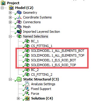
Transferred Element Sets: Specify Element Sets for transfer. Element Sets become two separate element components with the designation
_TOPand_BOT. One element component coincided with the original Element Set and the other one lies at the end of the extrusion path.Transferred Edge Sets: Specify Edge Sets for transfer. Edge Sets are extruded to form surfaces (an Edge Set transfers to a surface element component).
- Numbering Offset
ACP automatically performs entity numbering within your Workbench project. To avoid overlap, entities of multiple solid models in one ACP setup are automatically renumbered. When different ACP or Mechanical models are combined in a single analysis system, there is also automatic renumbering.
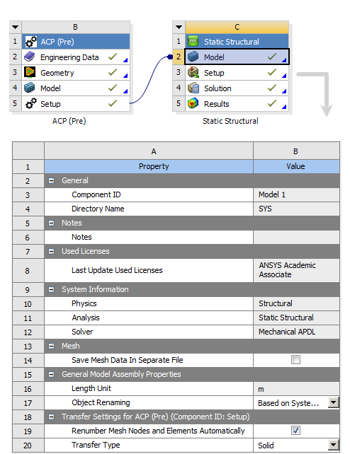
The automatic renumbering is activated by default and can be deactivated in the properties of the downstream Mechanical Model cell (see Renumber Mesh Nodes and Elements Automatically).
The entity numbering offset can also be controlled manually. Deactivate the Default option to define the offset manually for each of the entities (elements, nodes, materials, sections, coordinate systems). The numbering starts at the defined index and is incremented by one at a time.
The context menu of Solid Model and Imported Solid Model enables you to export the solid mesh itself or the skin (envelope) of the mesh in different formats.
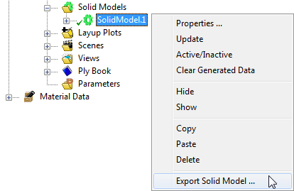
You can export the skin of the solid model as STEP, IGES, STL, or Mechanical APDL (CDB). These representations can be used, for instance, to construct the geometry of adjacent structures to the solid model or to construct the geometry of filling material in an airfoil structure. Note that the STEP and IGES geometries are built from a mesh based tessellation of the skin. Therefore, it might be worth to work with the STL format and the usage of reverse engineering tools (for instance in SpaceClaim) to construct a proper geometrical representation. The CDB format brings the benefit that you work without a geometry.
The analysis solid model itself can be exported as a CDB file. Element shape checking is deactivated in the exported file. Check that the material properties are consistent with the mesh units of the CDB file.
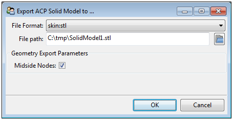
Midside Nodes: If available and active, the tessellation of the mesh includes the midside nodes of the quadratic elements. If not, only the corner nodes are considered. This option is only available for the formats skin:stp, skin:igs and skin:stl.
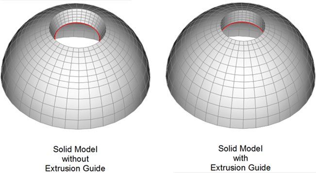
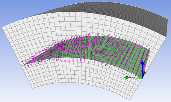
Solid Model generation for curved geometries and thick lay-ups can lead to boundary edges which are extruded in undesirable directions. For example, the extrusion of a dome with a hole at the top results in a solid model with a hole that is not cylindrical. The Extrusion Guide feature allows you to control the extrusion direction of the edges in order to rectify this. The edge of the hole can be used as an Extrusion Guide in the vertical direction to create a cylindrical hole.
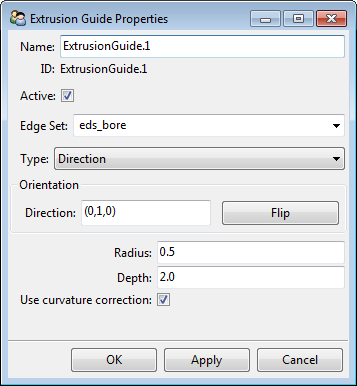
Multiple Extrusion Guides can be used for one Solid Model. The extrusion itself is controlled with an edge set and a direction vector or with a geometry. The Extrusion Guide feature also contains a Curvature Control. The Extrusion Guide Properties dialog has the following options:
Edge Set: Define the Edge Set along which the Extrusion Guide acts.
Type: The type of Extrusion Guide.
Direction: Defines a direction vector of the extrusion direction of the Edge Set.
Orientation Direction: By default, the normal direction of the Edge Set is calculated and defined when an Edge Set is selected. It can also be entered manually.
Geometry: CAD file of a boundary surface is used to define the extrusion path.
CAD Geometry: Select a previously generated Virtual Geometry. See CAD Geometries for information on how working with geometries impacts system performance.
Free: No extrusion path is defined but a curvature correction can be activated independently.
Radius: Controls the sphere of influence for mesh morphing.
Depth: controls the bias of the mesh morphing.
Use Curvature Correction: Apply a curvature correction during the solid model extrusion which results in a smoother extruded surface. Under certain circumstances, deactivating curvature correction can lead to better extrusion results.
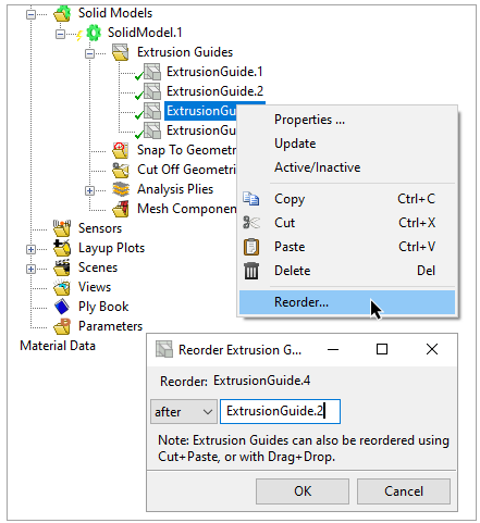
Extrusion Guides are excuted in the order they appear in the Tree. This has significant effects when Extrusion Guides intersect. You can change the order of Extrusion Guides from the Tree View, in one of the follows ways:
Use the cut-and-paste options in the context menu.
Use the cut (Ctrl+X) and paste (Ctrl+V) hotkeys.
Use the mouse to drag-and-drop the Extrusion Guides.
Use the Reorder option in the context menu, as shown below.
The generation of a solid model is by extrusion of a shell mesh. By default, extrusion is in the direction of the shell normal direction. The 2D shell mesh is used as a base for the 3D solid element mesh, which can have one or more element layers depending on the ply thickness and extrusion method.
The Extrusion Guide only affects the extrusion of the element edges that are part of the guided Edge Set. It is either defined by an Edge Set and direction vector or by an Edge Set and a CAD geometry. While the CAD geometry already is a surface, the Edge Set and direction vector helps define a surface. In both cases, these surfaces serve as target surfaces in the extrusion.
The guided edge is initially extruded in the normal direction. Then, the nodes on the resulting free surface are moved to coincide with the target surface of the Extrusion Guide.
Mesh morphing is a way to control the propagation of the Extrusion Guide effect through the entire mesh.
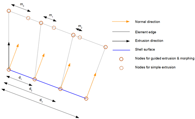
Mesh morphing is governed by the morphing law, shown in Equation 2–1. It relates the displacement of internal nodes to the displacement of a node of the guided free surface. Mesh morphing can be controlled with the two parameters:
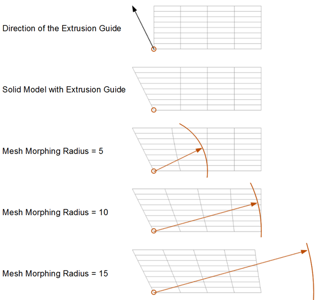
Radius: All elements within the defined Radius from the Edge Set are extruded with a mesh morphing correction.
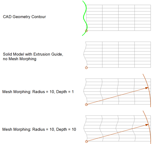
Depth: Defines the bias of the mesh morphing (linear with 1, quadratic with 2,...).
(2–1) |
where:
| m0 is the distance a node on the free surface has to move in-plane to coincide with the Extrusion Guide. |
| mi is the distance the inward node of the ith shell element moves in-plane as a result of the mesh morphing. |
| di is the distance between the node in the guided Edge Set and the inward node of the ith shell element. |
The following is an example of a direction-type Extrusion Guide with different mesh morphing radii. The location of the edge set is indicated by the circle in the bottom left corner. The mesh morphing is only applied to nodes on the shell surface whose distance to the Edge Set is smaller than the radius.
The following is an example of a geometry-type Extrusion Guide with different mesh morphing depths:
The Snap-To Geometry feature can alter an extruded Solid Model to align with an imported CAD Geometry. The layered Solid Model is locally stretched or compressed so that its selected faces coincide with the CAD geometry. Multiple Snap-To Geometries can be assigned to one Solid Model. The adaptation occurs at the first intersection that is found. See CAD Geometries for information on how working with geometries impacts system performance.
The feature is only applied to the selected Oriented Selection Set and its selected face (top or bottom). The normal orientation of the Oriented Selection Set defines which face is top or bottom. The height of all the elements through the thickness is altered to an even distribution.
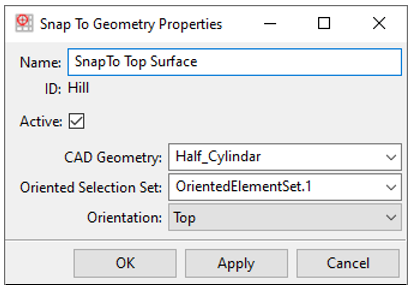
In the following example, the first picture shows the extrusion without any Snap-To Geometry operation. The lay-up is defined from two Oriented Selection Sets which point in opposite directions. In the second figure, the first Modeling Ply (oriented to the top) is defined to be extruded to a CAD Geometry. Only the nodes which meet the surface are extruded until the surface. The other nodes are extruded normally. The second Modeling Ply is extruded to another CAD Geometry in the last figure. For both cases, the orientation of the Snap-To Geometry operation must be top as the Oriented Selection Sets both point outward.
Caution: The Snap-To Geometry operation occurs after the Extrusion Guide operations. It is possible that the nodes moved during the Extrusion Guide operations are translated again, and do not match with the previous Extrusion Guide definition.
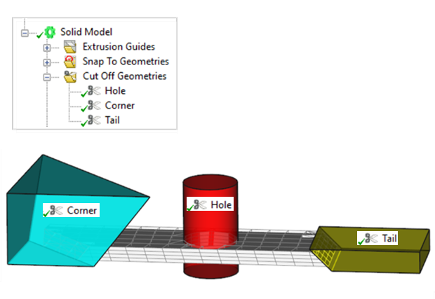
The Cut-Off Geometry feature uses CAD Geometries to shape the Solid Model by cutting off elements. The operation is analogous to machining a composite part after curing. Refer to Guide to Solid Modeling for more information. The following figures illustrate the Cut-Off Geometry feature:
Add a Cut-Off Geometry by selecting Create Cut-OffGeometry in the context menu of the Cut-Off Geometry folder.
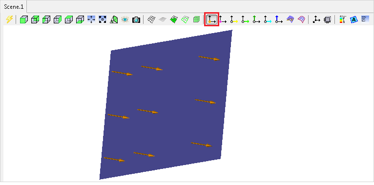
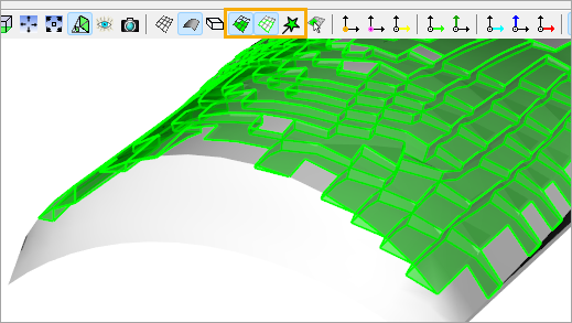
Define the Cut-Off operation with either a CAD surface geometry of CAD body geometry. The orientation flag specifies which side of the surface or the body the elements are cut off. The up orientation specifies that elements in the reverse normal direction of the geometry are cut off. A visualization of the surface normal direction of a CAD body geometry can be displayed with the button in the toolbar.
You can use multiple Cut-Off Geometries for one solid model. The cut offs are applied sequentially in order off Cut-Off Geometries creation.
The following properties must be defined in the Cut-Off Geometry Properties dialog:
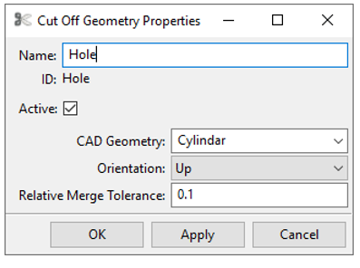
CAD Geometry: CAD geometry for surface or body geometry.
Orientation: Determines the cutting orientation of a surface/body geometry.
Relative Merge Tolerance: Set the merging tolerance for neighboring nodes relative to the element size. If two nodes fall within this tolerance they are merged, which avoids very small element edges.
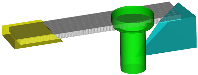
Note: Cut-Off operations are computationally intensive, so it is important to define your geometries efficiently. The Cut-Off algorithm runs faster if you create a for each part instead of creating a single geometry containing all parts. This is because ACP, prior to running the calculation, filters out all extraneous points and elements. The figure below illustrates the principle: Instead of one large geometry, three Cut-Off geometries have been added, one for each feature.
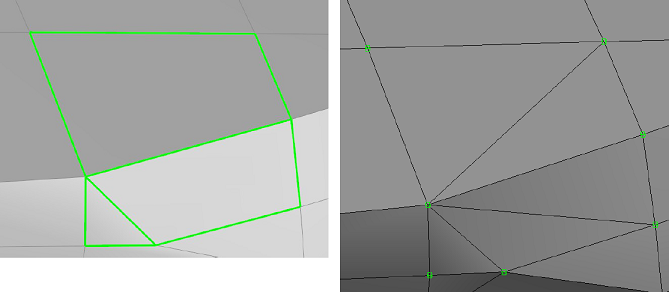
The cutting operation can reshape elements in such a way that they are no longer able to be handled by the solver. The Cut-Off elements are therefore decomposed into homogenous prism and tetrahedral elements following the Cut-Off operation. An example of such a decomposition is shown in the figure below. The decomposition takes place automatically during Solid Model generation.
Figure 2.146: A Degenerated Hexahedral Element (left) is Decomposed into Several Tetrahedral Elements (right)
The Cut-Off Geometry feature modifies elements by cutting off nodes. However, it does not refine the local mesh to conform precisely to the Cut-Off Geometry.
The sketch below illustrates how the Cut-Off Geometry Feature works: A node (a) of the finite element is within the Cut-Off Geometry, so it is removed from the element. But no additional nodes are added where the element edges intersect with the Cut-Off Geometry. Instead, the element is converted into a degenerated shape (B), in this case from a quad to a triangle. This also happens for 3D elements (prisms and hexes).
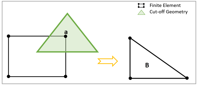
In many cases, the resulting element mesh will not represent all the features of the Cut-Off Geometry. This is especially true when the Cut-Off Geometry has sharp edges or features that are below the resolution of the elements. In the sketch shown below, for example, the finite element retains its shape because none of its nodes fall within the Cut-Off Geometry. To remedy this, you must refine the solid mesh by modifying the original shell mesh.
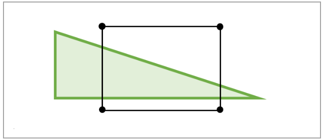
Another limitation is that degenerated elements (tetra elements, for example) do not support layered section data. Instead, the cut-off material, which is defined either in the Solid Model Properties or in the Fabric Properties, is assigned to the element. You can manage this by using the Analysis Ply-Wise Extrusion Method. Ansys recommends that you assess the results of cut-off elements carefully.
This folder contains Element Sets which were generated during the extrusion. For instance, the DropOffSet contains all Drop-Off elements. This is the area where the thickness of the solid elements drops to zero, and homogeneous elements are generated at the boundary.
You can select and highlight the mesh components in the Scene if the Element Selection Mode is set to Automatic or Solid (see Mesh Appearance).
The material handling for an analysis ply-wise extrusion follows the rules outlined in Fabric Solid Model Options. The following additional rules apply for other extrusion methods where plies of different materials are grouped together in one solid element layer.
Drop-Off Material Handling in Non-Analysis-Ply-Wise Extrusions
If the material handling option of at least one ply is set to Global, the global Solid Model Drop-Off material is used.
If all ply material handling options are set to Custom and refer to the same custom material, the custom Drop-Off material is used.
In all other cases (for example, a multi-layered solid with material handling options Custom and Global), the global Solid Model Drop-Off material is used.
Cut-Off Material Handling in Non-Analysis-Ply-Wise Extrusions
If the material handling option of at least one ply is set to Global, the global Solid Model Cut-Off material is used.
If all ply material handling options are set to Custom and refer to the same custom material, the custom Cut-Off material is used.
In all other cases, the global Solid Model Cut-Off material is used.
ACP Solid Models are saved as .H5 files. An update of ACP (Pre) component initiates a check of the current and previous laminate lay-up. While the laminate lay-up does not change no new solid model is generated.
By default, the solid model extrusion and the 3D lay-up representation used for the lay-up mapping within the Imported Solid Model are based on the ply thicknesses at the element center. If the Use Nodal Thickness is on (see Lay-up Computation), the solid model extrusion and 3D lay-up representation directly consume the node-based thicknesses, which can improve the accuracy. For more information, see the Element- vs. Node-based Thicknesses section.


