


The Options category is available for Coupled Field Harmonic, Harmonic Acoustics, and Harmonic Response analyses. However, not all of the properties described below may be applicable for each analysis type.
Go to a property description:
Frequency Spacing
This property defines how frequency spacing is performed. Options include: (default), , , , , , , and .
When you select the option, harmonic results are reported at uniform frequency intervals for the specified frequency range.
The option as well as the options define the Logarithm Frequency Spacing in a Harmonic Analysis by setting an appropriate LogOpt key for the HARFRQ command.
Central Frequency
This property displays when you select an option for the Frequency Spacing property. This property requires you to specify the central frequency of octave band.
Range Minimum and Range Maximum (Frequency Sweep Range)
You define a frequency sweep range by defining the Range Minimum and Range Maximum values when the Frequency Spacing property is set to or . When you set the Frequency Spacing property to an nth-Octave Band, you must also define a Central Frequency value. Based on the Central Frequency input, the Range Minimum and Range Maximum values are calculated and displayed as read-only. This information is useful when requesting a result at a particular frequency.
Solution Intervals
This property defines the number of the solution points between the frequency sweep range. You can request any number of harmonic solutions to be calculated. The solutions are evenly spaced within the specified frequency range, as long as clustering is not active.
For example, if you specify 10 (default) solutions in the range 30 to 40 Hz, the program calculates the response at 31, 32, 33, ..., 39, and 40 Hz. No response is calculated at the lower end of the frequency range.
This property is replaced by the Cluster Number property when you are using the Mode-Superposition Solution Method and the Cluster Results property is set to .
User Defined Frequencies
This property enables you to add additional frequency steps to your analysis. These frequency steps are in addition to the steps defined for the Frequency Spacing property. Options include: (default) and . When you specify , no additional frequency steps are included in the solution.
Specifying requires you to make entries in the Tabular Data window in the User Defined Frequency Steps column.
Important: If your analysis has multiple load steps, this property must be defined for each step.
The application executes the HARFRQ command using the FREQARR input (one dimensional array) to send data to the solver.
Note: The User Defined Frequencies capability is not supported for the following cases:
Cyclic Symmetry for a Harmonic Response analysis.
When the Solution Method property is set to .
Solution Method
The options of the Solution Method property, listed below, vary based on the harmonic-based analysis type. The option is only available for Harmonic Response analyses.
: The application selects the best solution method based on the model. Internally, the application chooses either the or solution method.
(default): See the Mode Superposition Method topic below for more information.
Note: The application automatically sets this property to and becomes read-only if you link your Harmonic Response analysis to a downstream Structural Optimization analysis or if the Future Analysis property (Analysis Settings > Analysis Data Management) is set to .
(Direct Integration): The Full method uses the full system matrices for the solution calculations. It is more thorough but also requires greater processing time and capability.
: Instead of using the full matrices to compute the results, the application computes the solution at the middle of the requested frequency range and then interpolates the system matrices and loading on the entire frequency range to approximate the results across the range.
Note: This setting is not supported when the Step Frequency Spacing property is set to . See the Step Controls for Harmonic Analysis Types section for more information.
For additional information, see Harmonic Response Analysis Variational Technology Method, and Variational Technology, as well as the HROPT command in the Command Reference.
: For pure acoustic Coupled Field Harmonic, pure acoustic Harmonic Acoustics, and Harmonic Response analyses, use this option to reduce the entire system of equations and build a Krylov Subspace set of vectors at the middle of the frequency range. The application solves this reduced system and then expands the solution over the entire frequency range.
Krylov Subspace Frequency: Specify the frequency at which the Krylov subspace is built. The default setting, , selects the middle of the frequency sweep range. The solution is most accurate at this frequency. You can observed this value using the Krylov Residual Norm result.
Limitation: The Distributed solution option is selected by default. For this setting, the automatic domain decomposition could select frequency-based decomposition during the solution. For this case, you cannot manually enter a value for this property.
Max Subspace Dimension: Specify the maximum dimension of the subspace. The default setting, , automatically determines this value (range of approximately 50). A larger value increases accuracy, however, it also increases processing time.
Residual Tolerance: Specify a tolerance value to verify the L2 norm values of the calculated residuals. The default value is
0.05.Note: If the application cannot achieve the specified residual tolerance throughout the entire frequency range, a warning message displays. For this case, Ansys recommends that you use the setting for the Solution Method property.
Be sure you review the following requirements and limitations.
Requirements and Limitations
- Limitations
For objects with options that make the system of matrices unsymmetric are not supported. For example:
Bearing objects can contribute to unsymmetric matrices if the stiffness coefficients K12 and K21 are not equal. Similarly, if damping coefficients C21 and C22 are not equal.
The Newton-Raphson Option set to is not supported for a linked pre-stressed Harmonic Response analysis.
The Coriolis Effect property under the Rotordynamics Controls group of the Analysis Settings object set to is not supported for a Harmonic Response environment or a Static Structural environment if linked to a pre-stressed Harmonic Response analysis.
The method is not supported if you specify any of the following:
A Contact Region with the Formulation property set to .
Joints whose Formulation property, Mobile or Reference category, is set to .
Remote Points with the Formulation property set to .
Cyclic Symmetry.
The Incident Wave Source excitation of a pure acoustic Coupled Field Harmonic or a pure acoustic Harmonic Acoustics analysis.
- Joint Support
Only the following joint configurations are supported:
Joints with the Type property set to and the Solver Element Type property set to .
Joints with the Type property set to and the Formulation property set to .
Mode Superposition Method
Mode Superposition is the default method for Harmonic Response analyses and generally provides results faster than the Full method. Using the Mode Superposition method, a modal analysis is first performed to compute the natural frequencies and mode shapes. Then the mode superposition solution is carried out where these mode shapes are combined.
When you specify the Mode Superposition option, additional properties become available, as listed below. However, the availability of these properties can differ based on whether the analysis is prestressed as well as based on the settings of other properties. The properties displayed when Mode Superposition is selected include:
- Include Residual Vector
This property is available for a Harmonic Response Analysis Using Linked Modal Analysis System and a stand-alone Harmonic Response Analysis when the Solution Method property is set to (default). When set to the application executes the RESVEC command and calculates or includes residual vectors. The default setting is . See the RESVEC command documentation in the Mechanical APDL Command Reference for additional information.
- Cluster Results and Cluster Number
Cluster Results: This property enables the solver to automatically cluster solution points near the structure’s natural frequencies ensuring capture of behavior near the peak responses. This results in a smoother, more accurate, response curve.
Cluster Number: This property specifies the number of solutions on each side of a natural frequency. The default is value is
4(to calculate four solutions). The range of available values is2to20. The following settings are required to display and define this property:Solution Method = Mode Superposition
Cluster Results = Yes
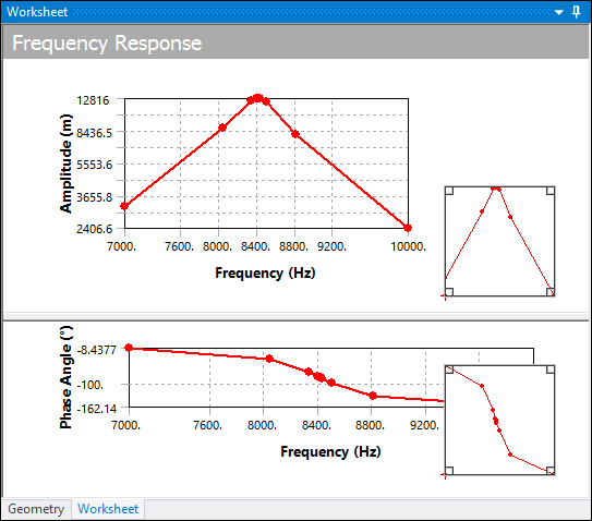
The following example illustrates a comparison of Solution Intervals versus clustering based on the different Solution Methods selections. You may also want to review the Automatic Frequency Spacing in a Harmonic Analysis section for a Harmonic Analysis in the Mechanical APDL Theory Reference.
Solution Intervals = 10: Here 10 solutions are evenly spaced within the frequency range. Note how the peak can be missed altogether.
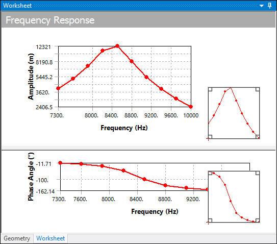
Cluster = 7: Here 7 solutions are performed automatically on either side of each natural frequency capturing the behavior near the peaks.
- Modal Frequency Range
Specifies the range of frequencies over which mode shapes will be computed in the modal analysis:
Program Controlled: The modal sweep range is automatically set to 200% of the upper harmonic limit and 50% of the lower harmonic limit. This setting is adequate for most simulations.
Manual: Allows you to manually set the modal sweep range. Choosing Manual displays the Modal Range Minimum and Modal Range Maximum fields where you can specify these values.
- On Demand Expansion Option
Options for this property include (default), , and . When set to , an additional read-only property, On Demand Expansion, displays. This property only displays for the option and the application determines the value for the property, either or . The application sets this property as when you request output controls or request fewer frequencies than the number of modes.
When the On Demand Expansion Option property is set to , either manually or from the setting, the application creates the result file optimally. That is, the application evaluates the results using the Modal solution data and calculates any other results "on demand." This improves solution performance and reduces file size. In addition, the application automatically removes mode shape data from the result file as determined by the On Demand Mode Shape preference (see note below).
Furthermore, the application supports the following result types only when this option is active (contour, frequency response, and probes):
Total and Directional Deformation
Total and Directional Acceleration
Total and Directional Velocity
Maximum, Middle and Minimum Principal Elastic Strain
Maximum Shear Elastic Strain
Elastic Strain Intensity
Normal Elastic Strain/Shear Elastic Strain
Equivalent Stress
Maximum, Middle and Minimum Principal Stress
Maximum Shear Stress
Stress Intensity
Normal Stress/Shear Stress
Force Reaction/Moment Reaction
Important:Force Reaction and Moment Reaction probes are only supported when scoped to a Boundary Condition.
Only the Frequency Response chart options , , and support Remote Point scoping.
The Moment Reaction probe is not supported on beam or shell bodies or when scoped to Remote Displacements.
You can change the default setting () of this property using the On Demand Expansion Option preference contained in the Options (Modal, Harmonic and Transient Mode Superposition) category of the Analysis Settings and Solution category of the Options dialog.
Also note that mode shape data is automatically removed from result files. You can change the setting of this process using the On Demand Mode Shapes preference, also contained under the Options (Modal, Harmonic and Transient Mode Superposition) category of the Analysis Settings and Solution category of the Options dialog.
- Store Results At All Frequencies
Upon solution, harmonic environments store data specified in the Output Controls for all intervals in the frequency range. Consequently, seeking additional results at new frequencies will no longer force a solved harmonic environment to be resolved. This choice will lead to a better compromise between storage space (results are now stored in binary form in the RST file) and speed (by reducing the need to resort to the solver to supply new results).
If storage is an issue, set the Store Results At All Frequencies to No. The application retains minimal data with this setting, providing only the harmonic results requested at the time of solution. As a result, the Output Controls do not control the availability of the results. This option is especially useful with frequency clustering.
Note: With this option set to No, the addition of new frequency or phase responses to a solved environment requires a new solution. Adding a new contour result of any type (stress or strain) or a new probe result of any type (reaction force, reaction moment, or bearing) for the first time on a solved environment requires you to solve, but adding additional contour results or probe results of the same type does not share this requirement; data from the closest available frequency is displayed (the reported frequency is noted on each result). Note that the values of frequency, type of contour results (displacement, stress, or strain) and type of probe results (reaction force, reaction moment, or bearing) at the moment of the solution determine the contents of the result file and the subsequent availability of data. Planning these choices can significantly reduce the need to re-solve an analysis.
- Mode Selection Method
This property displays when you are performing a Harmonic Response Analysis Using Linked Modal Analysis System. This property enables you to select the modes for the mode expansion. Property options include:
(default): This option expands all the extracted modes from the modal analysis. All the modes participate in the mode-superposition harmonic response analysis.
: When you select this option, the Significance Threshold property also displays. For the Significance Threshold property value, the application selects the modes that have a ratio for the Modal Effective Mass to the Total Mass that is greater than this value, in all directions, for expansion. That is, only the selected modes participate in the mode-superposition harmonic response analysis. The application default is
0.001. This feature improves the performance of postprocessing the modal results and reduces the file size.
For more information, see the Mode Selection Based on Modal Effective Mass section of the Mechanical APDL Structural Analysis Guide.
Krylov Method
Spin Softening
This property enables you to specify whether to include or exclude Spin Softening effect in the linear perturbation analyses. It is only available for a pre-stressed Harmonic Response analysis when the Solution Method is set to , , or . The options include (default), , and . The setting selects either to include or exclude Spin Softening in the solution based on whether the rotating reference frame attached to the body is fixed (Yes) or in motion (No). The option is invalid if the Coriolis Effect property (Rotordynamics Controls) is set to .
For more information, refer to the PERTURB command from MAPDL Command Reference Guide.