


The following procedure describes the general steps, for the different types of regions, that you’ll use to implement the symmetry feature during an analysis using the Mechanical Application. As needed, refer to Types of Regions section of the Symmetry documentation for more information about the specific region types.
Once you have imported your model into Mechanical, select the Model object and select the Symmetry option from the Model Context Tab. Alternatively, you can right-click on the Model object or within the Geometry window and select > from the context menu.
Based on your analysis type, and symmetry needs, insert one of the following Symmetry objects:
Symmetry Region (only flexible body scoping is supported)
Linear Periodic (this object displays as a Symmetry Region object)
Specify the Scoping Method property: specify as Geometry Selection (default) or Named Selection. Based on your selection, one of the following properties is required.
- Geometry/Low Boundary/High Boundary
These properties are visible when the Scoping Method property is set to . You use this property to specify the desired geometric entity. Use the options of the Graphics Toolbar to make your selections.
For Periodic Region, Cyclic Region, and Pre-Meshed Cyclic Region objects, instead of a Geometry property, you are presented with the Low Boundary and High Boundary properties.
Each low/high selection can consist of one or more faces over one or more parts, but they must be paired properly. To be valid, each face/edge you specify as the Low Boundary must be accompanied by its twin for the High Boundary.
In addition, make sure that each selected face/edge and its twin belong to the same multibody part (although it is not necessary that they belong to the same body). Adjust your multibody parts as needed.
Note:For the Periodic Region and the Cyclic Region objects, your low/high selections are used to match the mesh of the two boundaries.
For a Pre-Meshed Cyclic Region object, it is assumed that the mesh is matched. This object does not influence the mesh.
- Named Selection/Low Selection/High Selection
These properties are visible when the Scoping Method property is set to . This field provides a drop-down list of available, and appropriate, user-defined Named Selections.
For Periodic Region, Cyclic Region, and Pre-Meshed Cyclic Region objects, instead of a Named Selection property, you are presented with the Low Selection and High Selection properties.
For a Periodic Region, Cyclic Region, or Pre-Meshed Cyclic Region object, like the Geometry Selection option, the Low Selection must correspond to the Low Boundary component and High Selection must correspond to the High Boundary component.
The mesh matching requirements are the same as those for a geometry selection.
For the Symmetry Region and Periodic Region objects, and as required, define the Type property. It provides a drop-down list of the following options:
These options essentially apply boundary conditions to the symmetry planes. The Type property options support specific analysis types. See the Symmetry Region section for a more detailed description of use of these options.
Specify the Coordinate System: Select an appropriate coordinate system from the drop-down list.
Symmetry Region: Only supports Cartesian coordinate systems.
Periodic Region, Cyclic Region, and Pre-Meshed Cyclic Region: Only supports cylindrical coordinate systems.
As needed, refer to the Coordinate Systems section, Initial Creation and Definition.
Based on your symmetry application, you may need to also specify one or more of the following properties:
Symmetry Normal (Symmetry Region only): Specify the normal axis from the drop down list that corresponds to the coordinate system that you chose.
Periodicity Direction: This option applies a Symmetry Region object with the property set to only. This axis should point into the direction (in user selected Coordinate System) the model should be translated. It might be different from Symmetry Normal property used for other Symmetry Region types.
Behavior: This property displays during a structural analysis for a Symmetry Region object that has the Type property set to . This property specifies the coupling behavior between the Low and High Boundaries. Options include:
(default): The application allows the specified Low Boundary and High Boundary to deform in different directions in order to enable the structure to "breathe."
: The application couples the specified Low Boundary and High Boundary. This forces the boundaries to experience the same deformation in same direction.
Refer to the Structural and Thermal Linear Periodic Symmetry topic for more information.
Apply To: This property displays when piezoelectric physics is present in a Coupled Field analysis that includes a Symmetry Region with the Type property set to . This property specifies the degrees of freedom (DOF) applied to the scoped geometry.
(default): You can specify Displacement and Voltage DOFs on the geometries of the Low Boundary and High Boundary.
: You can specify Displacement on the geometries of the Low Boundary and High Boundary.
: You can specify Voltage on the geometries of the Low Boundary and High Boundary.
Linear Shift: This option applies to a Symmetry Region object with the property set to only. This value (positive or negative) represents the increment applied to the node's location in the chosen Periodicity Direction.
Important: If you create more than one Symmetry Region object that is specified as , each object must have the same value for the property.
For a Pre-Meshed Cyclic Region only, define the following:
Number Of Sectors: The entry range is any real number greater than
2.Boundary DOF Orientation:
Relative Distance Tolerance: The default setting is and this setting uses a value of
-0.0001.
Symmetry Examples
The following example shows a body whose Symmetry Region was defined in the Mechanical application.
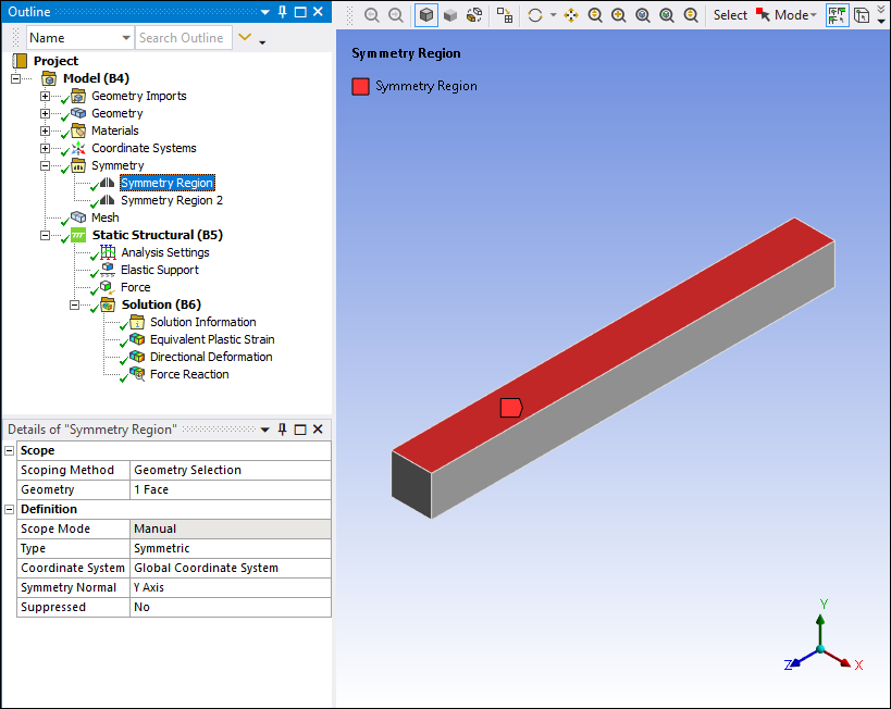
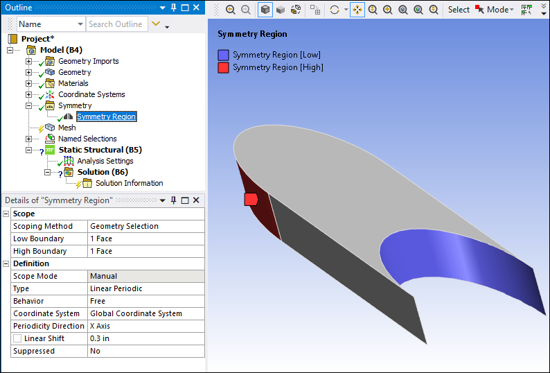
Note: You can select multiple faces to work with a symmetry region. For Symmetric/Anti-Symmetric Symmetry Regions, all faces selected (or chosen through Named Selection folder) must have only one normal. For Periodic/Cyclic types, you should additionally choose the proper cylindrical coordinate system with the z-axis showing the rotation direction, similar to the Matched Face Mesh meshing option. For a Symmetry Region with the Type property set to , you should choose the proper Cartesian coordinate system with the Periodicity Direction and Linear Shift properties showing pertinent values to facilitate conditions similar to the Arbitrary Match Control meshing option. In addition, the Behavior property also enables you to specify the coupling behavior between the Low and High Boundaries ( only).
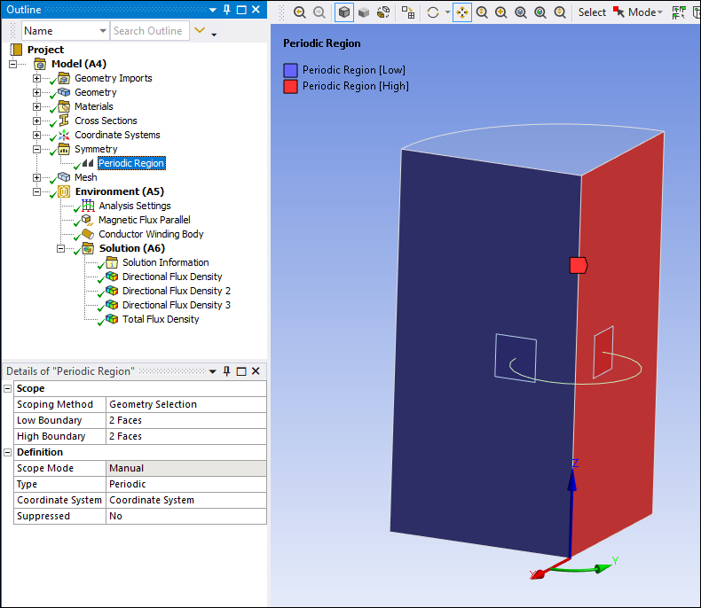
The following example shows a body whose Periodic Region was defined in the Mechanical application.
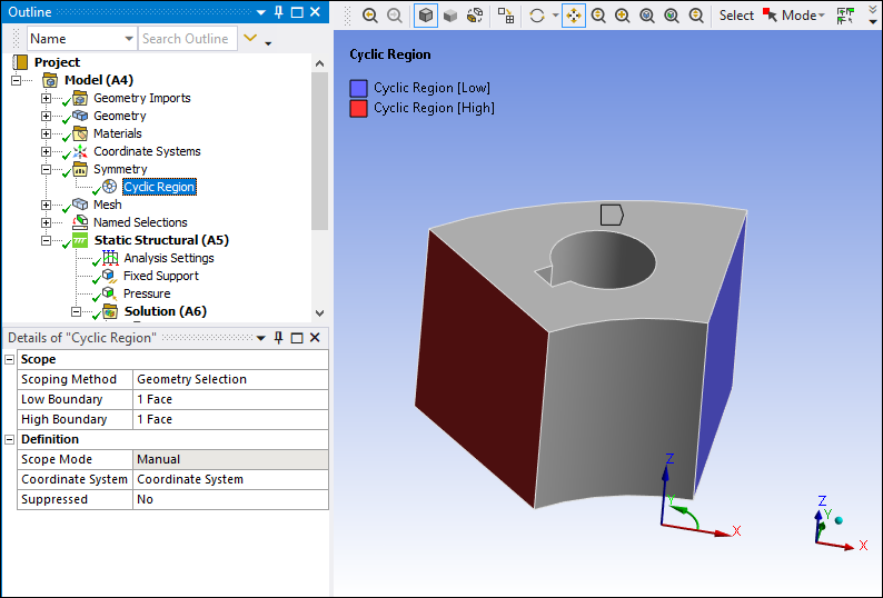
The following example shows a body whose Cyclic Region was defined in the Mechanical application.
Note:
When using a Periodic/Cyclic Region or for a Symmetry object whose Type is specified as , the mesher automatically sets up match face meshing on the opposite Low Boundary and High Boundary faces.
The application displays the following warning if the sector angle does not satisfy the calculation N * angle = 360, with tolerance of 0.5 degree.
Invalid sector angle : The angle (in degrees) spanned by the base sector should be such that N * angle = 360, where N is an integer and N should be same for all scoped bodies.
A useful feature available is the ability to swap Low Boundary and High Boundary settings under Scope in the Details view. You accomplish this by clicking the right mouse button on the specific symmetry regions (Ctrl key or Shift key for multiple selections) and choosing .
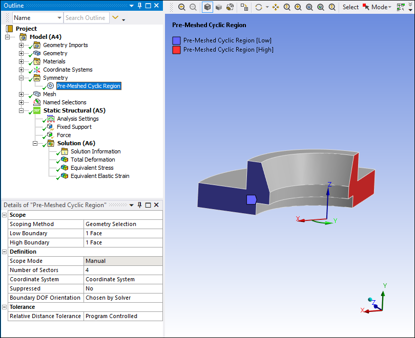
The following example shows a model defined with the Pre-Meshed Cyclic Region object in the Mechanical application.
Note: Except for cyclic symmetry models, symmetry models do not deform for unaveraged results. For example, for an unaveraged stress display, you will see the undeformed shape of the model.