Annotations provide the following visual information:
Boundary of the scope region by coloring the geometry for edges, faces or vertices.
An explicit vertex within the scope.
A 3D arrow to indicate direction, if applicable.
Text description or a value.
A color cue (structural vs. thermal, etc.).
Note: Custom annotations that you create using the Label feature remain visible even when you suppress the body.
This section addresses the following types of annotations:
| Highlight and Select Graphics |
| Scope Graphics |
| Annotation Graphics and Positioning |
| Annotations of Multiple Objects |
| Rescaling Annotations |
In addition, you can also specify preferences for your annotations. For more information, see Specifying Annotation Preferences.
Highlight and Select Graphics
You can interactively highlight and select topology, such as the face illustrated below. The topology selection highlights when you click it.
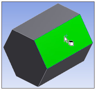
See Selecting Geometry for details on highlighting and selection.
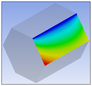
Scope Graphics
In general, selecting an object in the Outline displays its Scope by painting the geometry and displays text annotations and symbols as appropriate. The display of scope via annotation is carried over into the Report Preview if you generate a figure.
Contours are painted for results on the scoped geometry. No boundary is drawn.
Annotation Graphics and Positioning
A label consists of a block arrow cross-referenced to a color-coded legend. For vector annotations, a 3D arrow originates from the tip of the label to visualize direction relative to the geometry.
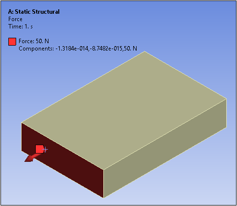
Use the pointer after selecting the option on the Graphics Toolbar for managing annotations and to drag the annotation to a different location within the scoping.
If other geometry hides the 3D point, for example, the point lies on a back face, the block arrow is unfilled (transparent).
The initial placement of an annotation is at the pick point. You can then move it by using the toolbar button for managing annotations.
Drag the label to adjust the placement of an annotation. During the drag operation the annotation moves only if the tip lies within the scope. If the pointer moves outside the scope, the annotation stops at the boundary.
Annotations of Multiple Objects
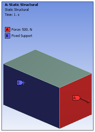
When multiple individual objects or a folder (such as environment, contact, or named selections) are selected in the Outline, an annotation for each one appears on the geometry. The default number of annotations shown is 10, but you can change it to any value from 0 to 50 using the Max Number of Annotations to Show property in the Graphics options of the Options dialog. For more information, see the Annotations topic in the Selection Tab section.
Note: If you have a large number of objects, you may want to display each object as a different color. See the Random option of the Annotations group.
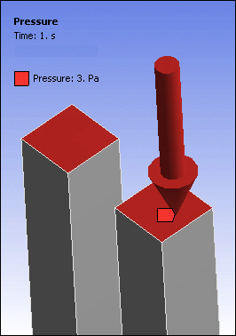
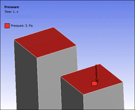
Rescaling Annotations
This feature modifies the size of annotation symbols, such as load direction arrows, displayed in the Mechanical application. For example, and as illustrated below, you can reduce the size of the pressure direction arrow when zooming in on a geometry selection. To change the size of an annotation, select the option in the Annotation group on the Display tab.